Instruction Sheet Betriebsvorschrift für Schütze 100-G550, 100-G700 und 100-G860 Operating Instructions for Contactors 100-G550, 100-G700 and 100-G860 Instructions de Service pour Contacteurs 100-G550, 100-G700 et 100-G860 Istruzioni per l'impiego dci Contattori 100-G550, 100-G700 e 100-G860 1 Publication 100G-IN001A-ML-P - May 2000
Important User Information Because of the v ariety of uses for the products descri bed in this publication, those re sponsible for th e a pplication an d use of this control equipment must s atisfy themselves that all necessary s teps have bee n taken to assure th at each application a nd use meets all performance and safety req uirements, incl uding any a pplicable laws, regulations, code s and standards.
European Communities (EC) Directive Compliance If thi s p roduct has the C E mark it is appr oved f or in stallation w ithin the Europe an Un ion a nd EEA regions. It h as been designed and tested to meet the fo llowing directives.
Betriebsvorschrift für Schütze 100-G550, 100-G700 und 100-G860 Operating instructions for contactors 100-G550, 100-G700 and 100-G860 Instructions de service pour contacteurs 100-G550, 100-G700 et 100-G860 Istruzioni per I’impiego dci contattori 100-G550, 100-G700 e 100-G860 UL/cUL Requirements • Break all lines. • Suitable for use on a circuit capable of delivering not more than 18000 RMS symmetrical amperes. 600V maximum. • Power terminations: Use 75°C copper conductors only.
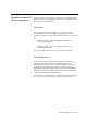
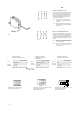
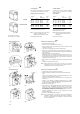
D Hilfsschalterblock EF 22 Der Hilfsschalterblock EF 22 ist mit 2 S und 2 Ö bestückt, die galvanisch getrennt sind. Der Einschaltzeitpunkt der Hilfsschliesser gegenüber den Hauptkontakten kann durch Drehen der Einstellschraube an der Frontseite justiert werden (siehe Fig. D). Fig.1 Fig. 1 – Lieferzustand – EF 22 links im Schütz montiert, zwischen L1 und L2. Fig. 2 – EF 22 rechts im Schütz montierbar, zwischen L2 und L3.
EN Auxiliary contact type EF 22 EF 22 auxiliary contact block provides 2 NO and 2 NC auxiliary contacts mutually insulated up to 690 V. NO contacts position related to the main poles can be regulated by the user screwing or unscrewing the adjustable screw shown on the contact block front (see Fig. d). Fig.1 Fig. 1 — EF 22 fitted L.H.S. on the contactor (between L1 and L2) delivered with the contactor. Fig. 2 — EF22 for fitting R.H.S.on the contactor (between L2 and L3) delivered separate as accessory.
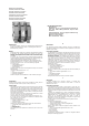
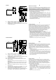
100-G550 1 C 3 A1 A2 1 2 DELAYED DROP 5 1AC 3 - 2AC Elektrisches Schaltbild NORMAL DROP + C1 3 4 2 4 4 6 C M1 C M2 1 13 21 31 43 53 61 71 83 14 22 32 44 Y 54 62 72 84 Y 3 5 C1 A1 A2 M1 M2 C NC NO Y NO NC 2 C: C1: C Y 4 100-G700/100-G860 A1 1 C 3 A2 1AC 4 6 - 2AC R Z+ 53 61 71 83 Electrical diagram 54 62 72 84 Y 3 5 C1 A1 D A2 M1 M2 Z M1 C M2 C C 4 C: C1: - RT 2 14 22 32 44 Y R R 1 13 21 31 43 F Le contacteur est livré déjà précâblé
Zubehör D Accessoires F Das Zubehör wird getrennt geliefert und muss vom Anwender angebaut werden. Les accessoires sont livrés non montés sur les contacteurs. Leur montage doit être effectué par l'utilisateur. Beschreibung Description Hilfsschalterblock 2 S + 2 Ö - Ith = 16 A «S» Kontakte einstellbar 1 zusätzlicher Hilfsschalterblock nachrüstbar pro Schütz 4. Pol (Schalten des Nulleiters) für 100-G550/ Ith = 500 A für 100-G700/ Ith = 500 A für 100-G860/ Ith = 1000 A Typ/ Bestell-Nr.
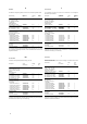
D F Austauschen der Spulen Échange des bobines Bestellangaben für Standard-Spulen Références de commande des bobines standard Weil das Schütz mit 2 in Reihe geschalteten Spulen bestückt ist, müssen diese 2 Spulen zusammen ausgetauscht werden. Spannungen 1) 100-G550 100-G700/100-G860 Satz von 2 Ersatzspulen Jeu de 2 bobines Les contacteurs étant équipés de 2 bobines branchées en série, il faut systématiquement procéder à l'échange des 2 bobines. Typ/ Bestell-Nr. Verp.
Coil Changing EN The contactors are equipped with 2 coils series connected and both coils have to be changed. Ordering details for standard coils Voltages 1) Cambio bobine I I contattori sono forniti con 2 bobine collegate in serie. In caso di sostituzione è necessario cambiarle entrambe. Tabella bobine Type/ Ordering No. Pack Qty Tensioni 1) Tipo/ N. di ordine V A.C. V D.C. V AC V DC 100-G550 110...120 220...240 380...415 440...480 100...110 200...220 345...380 400...
100-G550 normal drop delayed drop delayed drop 1AC - 3 TXS... normal drop 2AC 4 + D F Versorgungseinheit Module d'alimentation • Die Versorgungseinheit ermöglicht es, die Schützspulen wahlweise mit Wechselspannungen 50 Hz oder 60 Hz, bzw. Gleichspannungen zu betätigen. Zu jeder Spulenspannung gehört eine besondere Versorgungseinheit. Le module d'alimentation permet d'alimenter, indifféremment, la bobine du contacteur en alternatif 50 ou 60Hz ou en courant continu.
100-G550 normal drop delayed drop Feeder group EN I Modulo di alimentazione • The feeder group is suitable for A.C. 50 or 60 Hz or D.C. supply and has to be selected according to the supply voltage in force. Note: delayed drop delayed drop 1AC - 3 TXS... 2AC 4 + normal drop normal drop In case of a change in the control voltage supply which would require a coil changing, the feeder group has to be changed too.
100-G700/100-G860 D ZZ+ TYS... Module d'alimentation • Die Versorgungseinheit ermöglicht es, die Schützspulen w ahlweise mit Wechselspannungen 50 Hz oder 60 Hz, bzw. Gleichspannungen zu betätigen. Zu jeder Spulenspannung gehört eine besondere Versorgungseinheit • Le module d'alimentation permet d'alimenter, indifféremment, la bobine du contacteur en alternatif 50 ou 60 Hz ou encourant continu. À chaque tension bobine correspond un module d'alimentation.
100-G700/100-G860 Feeder group EN I Modulo di alimentazione • The feeder group is suitable for A.C. 50 or 60 Hz or D.C. supply and has to be selected according to the supply voltage in force. Note: ZZ+ TYS... In case of a change in the control voltage supply which would require a coil changing, the feeder group has to be changed too. • The feeder group is designed so that the user can select the contactor opening times as follows: — «normal drop» 150 to 200 ms. — «delayed drop» 0,5 to 1 sec.
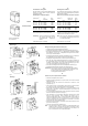
Massbilder/Encombrements Dimensions/Ingombri-Dimensioni [mm] 100-G550 100-G700/100-G860 Type A B C D E F 100-G700 138.5 15 13.5 8 13 307 100-G860 162.5 18 40.
Publication 100G-IN001A-ML-P - May 2000 2000 Rockwell International. All Rights Reserved.