
Manual

42052-089
G. Ushakow
N/A
N/A
N/A
42052
10064901
INSTRUCTION SHEET
BULLETIN 1102C 400A/600A VACUUM CONTACTOR
CONTROL-PAK
2-20-04
Mark Jutz 2-20-04
D. Josef 2-20-04
22
REVISION
AUTHORIZATION
DIMENSIONS APPLY BEFORE
SURFACE TREATMENT
H
A
B
C
D
E
F
G
(DIMENSIONS IN INCHES)
TOLERANCES UNLESS
OTHERWISE SPECIFIED
REFERENCE
SHEET OF
DWG.
B
DR.
CHKD.
APPD.
DATE
DATE
DATE
±
±
±
ANGLES:
.XXX:
.XX:
THIS DRAWING IS THE PROPERTY OF
THE ALLEN-BRADLEY CO. INC.
AND MAY NOT BE COPIED, USED OR
DISCLOSED FOR ANY PURPOSE EXCEPT
AS AUTHORIZED IN WRITING BY
THE ALLEN-BRADLEY CO. INC.
LOCATION : MILWAUKEE, WISCONSIN U.S.A.
SIZE
12345678
E - DOC
Control-Pak Replacement (Cont'd)
42052-089-01 (1)
Printed in U.S.A.
PART
NO.
MATERIAL
CHG.
CHAR.
SIZE
FLAT FOLD
-01
1
TWO SIDES PRINTED
8-1/2" W x 11" H
BODY STOCK WHITE
BODY INK BLACK
4-1/4" W x 5-1/2" H
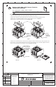
6. Install the new Control-Pak (Figures 3A & 3B). First, rotate the Retainer upwards. Next, insert the lower tab into
the recess on the side of the contactor base. With proper installation, the Actuator will fit into the hole in the slot in the
side of the contactor housing. Using a thin rod or flat blade, push the Actuator up or down as necessary to insert it into
the slot mentioned. Rotate the Retainer to its original position, which will slide over the upper tab on the Control-Pak.
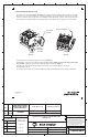
7. Confirm position of (2) retainers (adjust if necessary) (See Figure 1).
8. Reinstall the cover and secure it with the original mounting hardware. NOTE: Cover must fit under metal bracket
on Control-Pak. Tighten the four screws in a diagonal pattern to 5 lb-inches. (Figure 1).
9. Reattach the coil wire leads and any auxiliary control wires to the Control-Pak (tighten to 7 lb-inches).
10. Reinstall the contactor.
11. Reconnect the line and load conductors and tighten the main terminal hardware and bolts to 180 - 210 lb-inches.
Actuator
must fit into
slot shown
Figure 3A Figure 3B
Control-Pak
Actuator
Thin rod or flat blade