USB Converter 1203-USB Instruction Manual D2-3559
Solid state equipment has operational characteristics differing from those of electromechanical equipment. Safety Guidelines for the Application, Installation, and Maintenance of Solid State Controls (Publication SGI1.1 available from your local Rockwell Automation sales office or online at http:// www.rockwellautomation.com/literature) describes some important differences between solid state equipment and hard-wired electromechanical devices.
CONTENTS Chapter 1 Introduction 1.1 Related Documentation ................................................................................... 1-1 1.2 Manual Conventions ........................................................................................ 1-1 1.3 Getting Assistance from Reliance Electric....................................................... 1-1 Chapter 2 About the USB Converter 2.1 Components ................................................................................................
Appendix A ................................................................................................................................. A-1 Appendix B ................................................................................................................................. B-1 Appendix C ................................................................................................................................. C-1 Appendix D ..................................................................
CHAPTER 1 Introduction This manual is intended for qualified electricians familiar with installing, programming, and maintaining AC drives. This manual contains information on: • Installing and configuring the converter • Programming the converter • Troubleshooting the converter 1.1 Related Documentation Title 1.2 Publication Available Manual Conventions Parameter names: In most instances, parameter names are shown as the parameter name followed by the parameter number.
1-2 USB Converter User Manual
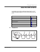
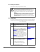
CHAPTER 2 About the USB Converter The 1203-USB converter provides a communication interface between a computer and any Reliance Electric product implementing DPI (SP600, LiquiFlo 2.0, and GV6000) or MDI (MD60 and MD65). The converter uses the full-duplex, RS-232 DF1 protocol. Topic 2.1 Page Components 2-1 Features 2-2 Compatible Products 2-3 Required Equipment 2-3 Safety Precautions 2-4 Quick Start 2-4 Modes of Operation 2-6 Components ➊ ➍ ➎ ➏ ➋ ➌ Figure 2.
Table 2.1 – Components of the Converter Item 2.2 Part Description ➊ Computer Cable Port The USB cable is plugged into this connector. ➋ Status Indicators LEDs that indicate converter operation, data is being received from the computer, and data is being sent to the computer. Refer to Chapter 5, Troubleshooting, for more information. ➌ Drive Cable Port DPI Drives: Plug the 20-OIM-H10 cable into this port. MDI Drives: Plug the 22-OIM-H10 cable into this port.
2.3 Compatible Products The 1203-USB converter can be used with Reliance Electric products that support DPI or MDI. At the time of publication, compatible products include: DPI Products • SP600 • GV6000 • LiquiFlo 2.0 MDI Products 2.4 • MD60 • MD65 Required Equipment 2.4.
2.5 Safety Precautions Please read the following safety precautions carefully. ATTENTION: Risk of injury or equipment damage exists. Only personnel familiar with drive and power products and the associated machinery should plan or implement the installation, start-up, configuration, and subsequent maintenance of the product using the converter. Failure to comply may result in injury and/or equipment damage. ! ATTENTION: Risk of injury or equipment damage exists.
Pocket PC, Laptop or Desktop Computer DPI Drive 1203-USB Converter USB Cable 20-OIM-H10 Cable Figure 2.2 – Connecting the Converter to a DPI Drive and Computer Pocket PC, Laptop or Desktop Computer MDI Drive 1203-USB Converter 20-OIM-H10 Cable USB Cable Figure 2.
2.7 Modes of Operation The converter reports its status using the status indicators (Figure 2.4). ➊ ➋ ➌ Figure 2.4 – Status Indicators on the Converter The following table describes the state of the status indicators under normal operation: Table 2.3 – Status Indicator Descriptions Item ➊ ➋ ➌ Status Indicator Diamond TX RX Normal State Description Flashing Green Converter is connected to a compatible product. Solid Green Converter is or was receiving control I/O.
CHAPTER 3 Installing the Converter Chapter 3 provides instructions for installing and removing the 1203-USB converter. Topic 3.1 Page Selecting Cables 3-1 Installing the Converter 3-2 Installing the USB Drivers 3-3 Installing V*S Utilities 3-6 Removing the Inverter 3-6 Selecting Cables Only two of the three supplied cables are required to install the 1203-USB converter. Always use the USB cable to connect the converter to the computer.
Table 3.1 – Cable Descriptions (DPI) Item Description ➊ DPI cable to connect the converter to a DPI drive. ➋ USB cable to connect the converter to the computer. Catalog Number 20-OIM-HIO ➊ ➋ Figure 3.2 – Cables for Connecting to a MDI Drive and Computer Table 3.2 – Cable Description (MDI) Item Description ➊ MDI cable to connect the converter to a MDI drive. ➋ USB cable to connect the converter to the computer.
(20-OIM-H10 cable for a DPI drive or 22-OIM-H10 cable for a MDI drive). Figure 3.3 – Conneting the Converter to the Drive 2. Connect the converter to the computer (Figure 3.4) using the USB cable. Verify that power is applied to the drive. The 1203-USB converter receives power from the drive, so the drive must be powered before the converter will operate,. Figure 3.
appear. Figure 3.5 – USB Converter Found New Hardware Wizard Screen 2. Insert the V*S Utilities CD into your computer. The V*S Utilities Setup screen appears while the computer automatically searches for and loads the 1203-USB driver from the inserted CD. 3. Keep the V*S Utilities CD inserted in the computer. On the V*S Utilites Setup screen, click Close. 4. After the 1203-USB driver has been successfully installed, a confirmation screen (Figure 3.6) appears. Click Finish.
Figure 3.6 – Completing the Found New Hardware Hardware Wizard Screen 5. After approximately 20 seconds, the USB Serial Port “Found New Hardware Wizard” screen (Figure 3.7) should appear. Figure 3.7 – USB Serial Port Found New Hardware Wizard Screen 6. With the “Install the software automatically (Recommended)” radio button selected (Figure 3.7), click Next >. The computer automatically searches for and loads the USB Serial Port driver from the inserted V*S Utilities CD.
7. After the USB Serial Port driver has been successfully installed, a confirmation screen (Figure 3.8) appears. Click Finish. Figure 3.8 – USB Serial Port Completing the Found New Hardware Wizard Screen 3.4 Installing V*S Utilities If you intend to use V*S Utilities as your configuration tool, you can install it while the V*S Utilities CD is still inserted in your computer. Launch the V*S Utilties CD to display the V*S Utilities Setup screen to install the software. 3.
CHAPTER 4 Configuring the Converter Chapter 4 provides instructions and information for configuring the 1203-USB converter. Topic 4.1 Page Configuration Tools 4-1 Using the DPI Class OIM 4-2 Using the MDI Class OIM 4-4 Using V*S Utilities 4-4 V*S Utilities Quick Start 4-5 Using Terminal Emulation Software 4-6 Resetting the Converter 4-8 Configuration Tools The 1203-USB converter stores parameters and other information in its own Non-Volatile Storage (NVS) memory.
4.2 Using the DPI Class OIM If you are connected to a DPI drive and it has an LED or LCD OIM (Operator Interface Module), you can use the OIM to access and edit parameters in the 1203-USB converter (see basic steps shown below). It is recommended that you read through the steps for your OIM before performing the sequence. For additional OIM information, refer to your DPI Drive User Manual. Table 4.2 – LED OIM Quick Start Step 1. Press ALT and then Sel (Device) to display the Device Screen. 2.
Table 4.3 – LCD OIM Quick Start Step 1. In the main menu, press the Up Arrow or Down Arrow to scroll to Device Select. Key(s) OR Example Screens F-> Stopped 0.00 M Hz Main Menu: Diagnostics Parameter Device Select 2. Press Enter to enter your selection. Port 2 Device 3. Press the Up Arrow or Down Arrow to scroll to 1203-USB. OR 1203-USB Main Menu: Diagnostics Parameter Device Select 4. Press Enter to select the converter.
4.3 Using the MDI Class OIM If you are connected to a MDI drive, you can use a MDI OIM (Operator Interface Module) to access and edit parameters in the 1203-USB converter (see basic steps shown below). It is recommended that you read through the steps for your OIM before performing the sequence. For additional OIM information, refer to the OIM Quick Reference card. Table 4.4 – Using the OIM Step Key(s) 1. Power up the drive. Then plug the OIM into the drive.
Important: For MDI drives, converter Adapter Cfg (01) must be set to “Auto” (default) for V*S Utilities to operate. If this parameter needs to be changed, HyperTerminal can be used to configure the converter (See “Using Terminal Emulation Software” on page 4-6.). 4.5 V*S Utilities Quick Start This section is designed to help you start using V*S Utilities. 1. Obtain and note the COM port that was assigned during installation of the 1203-USB driver. To do this: a.
5. In the left pane, click the Parameter List for the 1203-USB converter or connected drive to display its parameters in the right pane. Double-click a parameter to edit it. 4.6 Using Terminal Emulation Software This section provides detailed instructions on how to use terminal emulation software to access the 1203-USB converter so that you can view and edit its parameters or view its event queue.
4. Click OK to display the Connect To screen (Figure 4.3). Figure 4.3 – Connect To Screen 5. From the “Connect using” pulldown list, select the communications port noted in Step 1 on Page 4-5. 6. Click OK to display the COM Properties screen (Figure 4.4). 7. Select the settings shown in Figure 4.4. Figure 4.4 – COM Properties Screen 8. Click OK. A blank HyperTerminal workspace appears. Important: Select File > Save to save the HyperTerminal configuration that you just created.
9. Press the Enter key until the main menu (Figure 4.5) appears. Main Menu - Enter Number for Selection 1> Display Setup Parameters 2> Display Event Queue 3> Flash Upgrade Figure 4.5 – Main Menu If no text or meaningless text appears instead of the Main Menu, it is possible that a baud rate other than “115200” was selected See step 7 on page 4-7. 4.6.2 Navigating in the Terminal Emulation Software Table 4.5 – Key 0 ... 9 In the main menu, keys 1 – 3 select a menu option.
When you select Reset Module, the converter will be immediately reset. When you select Set Defaults, the converter will set all converter parameters to their factory-default values. After performing a Set Defaults, select Reset Module so that the new values take effect. The value of this parameter will be restored to Ready after the converter is reset.
4-10 USB Converter User Manual
CHAPTER 5 Troubleshooting Chapter 5 provides information for troubleshooting potential problems with the 1203-USB converter. Topic 5.1 Page Understanding the Status Indicators 5-1 Converter Diagnostic Items 5-4 Viewing and Clearing the Event Queue 5-5 Viewing and Clearing DFI Communication Statistics 5-8 Troubleshooting Potential Problems 5-9 Understanding the Status Indicators The converter has three status indicators to report its operating status(Figure 5.1). ➊ ➋ ➌ Figure 5.
! ATTENTION: Risk of injury or equipment damage exists. If the converter is transmitting control I/O to the drive (indicated by a solid green diamond LED), the drive may fault when you remove or resetthe converter. Determine how your drive will respond before removing or resetting a converter. Table 5.2 – Diamond Status Indicator Status Off Cause Converter is not powered or is in Flash programming mode. Corrective Action • Securely connect cables. • Apply power to the drive.
Table 5.3 – RX Status Indicator Status Off Cause Converter is not receiving data. Flashing Green Converter is receiving data from the computer. Corrective Action • Verify that data is being transmitted by the PC. • Securely connect cables. • Apply power to the drive. • Configure the computer software to use the same port rate as the converter. No action required. Table 5.4 – TX Status Indicator Status Off Flashing Green Troubleshooting Cause Converter is not transmitting data.
5.2 Converter Diagnostic Items Converter diagnostic items can be viewed using V*S Utilities (version 4.06 or higher). If you encounter unexpected communication problems, diagnostic items can help you or Reliance Electric personnel troubleshoot the problem. Table 5.5 – For DPI Drives No. 5-4 Name Description 1 Common Logic Cmd Present value of the Common Logic Command being transmitted to the drive by the converter.
Table 5.6 – For MDI Drives No. 5.3 Name Description 1 Field Flash Cnt Number of times the module has been Field Flashed. 2 Adapter Events Number of events in the event queue. 3 Reference Present value of the Reference being transmitted to the drive by the converter. 4 Logic Cmd Present value of the Logic Command being transmitted to the drive by the converter. 5 Logic Sts Present value of the Logic Status being received from the drive by the converter.
5.3.2 Events Many events in the Event queue occur under normal operation. If you encounter unexpected communications problems, the events may help you or Reliance Electric personnel troubleshoot the problem. The following events may appear in the event queue: Table 5.7 – For DPI Drives Events 5-6 Description Control Disabled The converter has sent a “Soft Control Disable” command to the DPI drive. Control Enabled The converter has sent a “Soft Control Enable” command to the DPI drive.
Table 5.7 – For DPI Drives Events Description Type 0 Time Flt The converter has not received a type 0 status message within the specified time. Use I/O Sent The converter has begun sending drive-specific control information. Press the UP ARROW or DOWN ARROW key to scroll through the parameter list. Press the LEFT ARROW or RIGHT ARROW key to modify parameter values. Press the ENTER key to save a new value. 1> Clr Event Queue = Enable Figure 5.
5.3.3 To clear the event queue 1. Access the 1203-USB event queue using a configuration tool (See “Configuration Tools” on page 4-1.). 2. Set the 1 > Clr Event Queue parameter to Enable, and then press Enter to clear the event queue. 5.4 Viewing and Clearing DF1 Communication Statistics If you encounter unexpected communications problems or are creating an application that uses DF1 data, you can view the communications statistics stored in the converter.
5.5 Troubleshooting Potential Problems Table 5.9 – Troubleshooting Potential Problems Description You are unable to establish a connection between the computer and converter. After changing the software tool’s port rate, you are no longer able to communicate with the converter and connected drive. For example, in HyperTerminal, meaningless text appears on the screen when you press Enter. In V*S Utilities, parameter values are not updated.
Table 5.9 – Troubleshooting Potential Problems 5-10 Description Action You are connected to a DMDI drive, converter Adapter Cfg (04) is set to “4” (RTU Passthru), and the diamond status indicator is flashing red. Power cycle the drive to which the converter is connected. Then do one of the following: • HyperTerminal – Connect to the drive through the converter. Then simultaneously press the Ctrl and P keys as your initial command (instead of Enter). • V*S Utilites (v4.
APPENDIX A Specifications Appendix A presents specifications for the 1203-USB converter. Topic Page Communications A-1 Electrical A-1 Mechanical A-2 Environmental A-2 Agency Certification A-3 Communications Network side Protocol Port Rate Data Bits Parity Stop Bits Flow Control Error Universal Serial Bus (USB) 115.2 kbps 8 None 1 None CRC or BCC (Auto-Detected) Drive side Protocol Data Rates (bps) DPI 125K/500K MDI 19.
Mechanical Dimensions Height Width Depth 103.5 mm (4.08 inches) 73.4 mm (2.89 inches) 23.6 mm (0.93 inches) Weight 70.88 g (2.5 oz.) Environmental Temperature Operating Storage 0 to 50°C (32 to 122°F) -40 to 85°C (-40 to 185°F) Relative Humidity 5 to 95% non-condensing Atmosphere Important: The converter must not be installed in an area where the ambient atmosphere contains volatile or corrosive gas, vapors or dust.
Agency Certification UL UL508C cUL CAN / CSA C22.2 No. 14-M91 CE EN50178 and EN61800-3 CTick AS / NZS 2064, Group 1, Class A Important: For this product to be CE and CTick compliant, the shield of the drive cable must be terminated as described on page A-2. Note : This is a product of category C2 according to IEC 61800-3. In a domestic environment this product may cause radio interference in which case supplementary mitigation measures may be required.
A-4 USB Converter User Manual
APPENDIX B Converter Parameters Appendix B provides information about the 1203-USB converter parameters. Topic Page Parameter List for DPI Drives B-1 Parameter List for MDI Drives B-3 Parameter List for DPI Drives No. 01 Name and Description DPI Port Displays the port on the host drive to which the converter is connected. Details Default: 0 Minimum:0 Maximum:7 Type:Read Only 02 Reset Module No action if set to “Ready.” Resets the converter if set to “Reset Module.
No. 03 04 Name and Description Details Clear DF1 Counts No action if set to “Ready.” Resets the DF1 statistical parameter DF1 Packets Sent (04) and DF1 Packets Rcvd (05) to 0 if set to “Clear Counts.” This parameter is a command. It will be reset to “0 = Ready” after a “Clear Counts” command has been performed. Default: 0 = Ready Values: 0 = Ready 1 = Clear Counts Type: Read/Write DF1 Packets Sent Displays the number of DF1 packets sent by the converter.
Parameter List for MDI Drives No. 01 Name and Description Adapter Cfg Sets the operation of the converter on MDI. Leave at “Auto” (setting) when used with software tools. Important: Adapter Cfg (01) must be set to “Auto” (default) for V*S Utilites to operate. HyperTerminal can be used if this parameter needs to be changed (see Using Terminal Evaluation Software on page 4-11). 02 Reset Module No action if set to “Ready.” Resets the converter if set to “Reset Module.
No. 05 06 07 08 B-4 Name and Description Details [DF1 Packets Rcvd Displays the number of DF1 packets received by the converter. The value of this parameter is normally approximately equal to the value of DF1 Packets Sent (04). Default: 0 Type: Read Only RTU DSI Addr Cfg Sets the node address of the converter for use with the converter operating mode set with Adapter Cfg (01). In Auto, Master or Slave mode, the converter node address can be any valid value.
APPENDIX C Flash Updates Appendix C provides information on flash updating host or peripheral product firmware. Topic Page Preparing for Flash Update C-1 Performing a Flash Update with V*S Utilities C-2 Performing a Flash Update with HyperTerminal C-7 Troubleshooting HyperTerminal Flash C-9 Preparing for a Flash Update Please take the following precautions to ensure a successful flash update: • Obtain the new firmware version from Rockwell Automation, Inc.
Performing a Flash Update with V*S Utilities V*S Utilities version 4.06 or higher can perform flash updates on products that use flash memory and implement DPI or MDI, such as DPI Class drives and peripherals or MDI Class peripherals. MDI Class drives can only be flash updated using a AK-U9-FLSH1 flash kit. This flash update procedure uses a PowerFlex 70 Enhanced Control drive as the example device being flashed.
Important: In the last screen, the ControlFLASH Setup Complete screen (Figure C.2), uncheck both boxes and click Finish. Figure C.2 – ControlFLASH Setup Complete Screen 3. Establish communications between the drive connected to the 1203-USB converter and the computer. For this procedure, please see “Using V*S Utilities” on page 4-4. 4. In the V*S Utilities application window (Figure C.3), click on the device to be flash updated (for this example, a PowerFlex 70 (Enhanced Control drive). Figure C.
5. Select Explore > Device Properties… to display the device’s information screen. Then click the Details tab to show a screen (Figure C.4) with the device’s firmware revision information. Figure C.4 – Details Tab Screen 6. In the Details tab screen, click the Flash Update… button to open the Select Flash Update screen (Figure C.5). Figure C.
7. In the Available Flash Updates window on this screen, select the appropriate firmware version from the list (for this example, 2.003.19 App). Then click Next> to continue. The Confirm Flash Update warning screen (Figure C.6) appears. Figure C.6 – Confirm Flash Update Warning Screen 8. Click FLASH to start the flash update (Figure C.7). If an advisory dialog box appears, follow the instructions. Figure C.
9. When the flash update is completed, the message window in the Executing Flash Update screen changes to indicate that flash update was completed (Figure C.8). Figure C.8 – Executing Flash Update Completed Screen Click Close to exit the Flash Update Completed screen. The Device Firmware Changed dialog box (Figure C.10) will appear. Figure C.9 – Device Firmware Changed Dialog Box 10. V*S Utilities will prompt you to reconnect since the device may have changed its database because of the flash update.
Performing a Flash Update with HyperTerminal 1. In the main menu (Figure 4.5), press 3 to flash upgrade. For connected MDI drives, you can only update the firmware in the converter. The screen in Figure C.11 will immediately appear. For connected DPI drives, a menu appears (Figure C.10) for you to select the device that you want to update. Flash Upgrade. Enter Number for Selection. 0 > PowerFlex 70 EC 1 > LCD Module 2 > This 1203-USB 5 > 20-COMM-D Figure C.
6. In the Protocol box, select “Xmodem.” Figure C.12 – Example Send File Screen 7. Click Send. A dialog box appears and reports the progress of the download. When it is complete, the message “Operation Complete” appears. Important: Keep the device powered for 15 seconds after the operation has completed. 8. Press the Enter key to return to the main menu.
Troubleshooting HyperTerminal Flash Problems Description Corrective Action The “Transfer Cancelled by Remote System” message appears and the flash is not completed. • Restart HyperTerminal and repeat the flash procedure. • If you are using Windows NT 4.0, install SP3 or later. Windows NT service packs are available from the Microsoft web site: http://www.microsoft.com. • Download a HyperTerminal Private Edition update from the Hilgraeve web site: http://www.hilgraeve.com.
C-10 USB Converter User Manual
APPENDIX D Using RTU Master Mode Appendix D provides information about using the 1203-USB converter in RTU Master mode. Topic Page Establishing Communications D-1 Configuring the Drive Parameters D-1 Configuring the Converter for RTU Master Mode D-4 Network Wiring D-4 Accessing Drives on the RTU Master Network D-6 With the converter in RTU Master mode, you can monitor, configure, and control up to 32 MDI Class drives using one of the Reliance Electric drive software tools.
Setting Drive Addresses 1. For Drive 1 connected to the 1203-USB converter, set drive parameter Comm Node Addr (104) to match the converter node address (default = 1) set with drive parameter RTU DSI Addr Cfg (06). Important: When setting the 1203-USB converter node address, do not use a value higher than “77” octal. 2. For each remaining drive to be networked, set drive parameter Comm Node Addr (104) to a unique address.
For your convenience, use the blank list below to note the settings for each drive to be networked.
Network Drive Number Address Setting for Drive Parameter Drive Addr Cfg (104) Comm Fault Setting for Drive Parameter Comm Loss Action (105) 29 30 31 32 Configuring the Converter for RTU Master Mode Using V*S Utilities 1. On the V*S Utilities 1203-USB Parameter List screen (Figure D.1), double-click converter parameter Adapter Cfg (01) and set its value to “3 = RTU Master.” Figure D.1 – V*S Utilities 1203-USB Parameter List Screen 2.
Using a 22-RJ45CBL-Cxx Communications Cable, or an appropriate twisted pair cable and an AK-U0-RJ45-TB2P terminal block connector (Figure D.3), insert the connector into the splitter cable Slave port (identified by the letter “S” at the port). Then insert the connector on the cable’s other end into Port 2 on the bottom of the second drive (Drive 2).
The AK-U0-RJ45-TB2P two-position terminal block connector (Figure D.3) can be used to conveniently daisy-chain the MDI Class drives from Drive 1, which is connected to the 1203-USB converter. Two terminating resistors are also included with terminal block connectors in the AK-U0-RJ45-TB2P kit. Figure D.3 – AK-U0-RJ45-TB2P Terminal Block Connector Figure D.4 shows a wiring diagram for using the AK-U0-RJ45-TB2P terminal block connectors.
Re-establish communications between the drives on the RTU Master network and the computer (via the 1203-USB converter). 1. Apply power to all of the drives on the RTU Master network. 2. In the V*S Utilities application window (Figure D.5), select Explore > Connect > Serial to Network… to display the Network Connection - Node Selection screen (Figure D.6). Figure D.5 – V*S Utilities Full Application Window Figure D.6 – Network Connection - Node Selection Screen 3. Select the “Multiple” radio button.
Important: If the network drive node address is valid, “Online” is shown next to the selected address. If a node address is not valid, “Offline” will appear. Figure D.7 – V*S Utilities Network Menu Tree 4. Click on each node in the menu tree to create its database and identity. Then expand each node to display the connected drive and 1203-USB converter representation (Figure D.8).
Using RTU Master Mode D-9
D-10 USB Converter User Manual
GLOSSARY A Application Code Code that runs in the converter after the boot code calls it. Application code performs the normal operations of the converter. B BCC (Block Check Character) An error detection scheme using the 2’s complement of the 8-bit sum (modulo-256 arithmetic sum) of all data bytes in a transmission block. It provides a means of checking the accuracy of each message transmission. Boot Code Code that runs when the converter first receives power.
DPI (Drive Peripheral Interface) A second generation peripheral communication interface used by various Reliance Electric drives. DPI (Architecture-Class) Drives The Reliance Electric DPI (Architecture-Class) family of drives include the SP600, GV6000, and LiquiFlo 2.0. These drives can be used for applications ranging from 0.37 kW (0.5 HP) to 3000 kW (4000 HP). DPI Peripheral A device that provides an interface between DPI and a network or user.
O OIM (Operator Interface Module) A device that can be used to configure and control a DPI drive or a MDI drive. DPI OIMs (20-OIM-xxx) and MDI OIMs (22-OIM-xxx) can be used to configure connected peripherals. N NVS (Non-Volatile Storage) NVS is the permanent memory of a device. Devices such as the converter and drive store parameters and other information in NVS so that they are not lost when the device loses power. NVS is sometimes called “EEPROM.
Glossary-4 USB Converter User Manual
INDEX A accessing parameters using DPI Class OIM, 4-2 using terminal emulation software, 4-6 Adapter Cfg parameter (only DSI drives), B-3 Adapter Type parameter (only DSI drives), B-4 adapter, see converter agency certification, A-3 application code, Glossary-1 B baud rate, see DF1 rate BCC (Block Check Character), A-1, Glossary-1 boot code, Glossary-1 bus off, Glossary-1 C cables connecting, 3-2 disconnecting, 3-6 checksum, A-1 Clear DF1 Counts parameter for DPI drives, B-2 for DSI drives, B-3 clearing e
DriveTools SP definition, Glossary-2 web site, Glossary-2 DSI definition, Glossary-2 E EEPROM, see NVS (Non-Volatile Storage) equipment required, 2-3 supplied, 2-3 error detection, A-1 event queue clearing events, 5-8 list of events, 5-6 M MDI definition, Glossary-2 peripheral, Glossary-2 product, Glossary-2 MDI drives, Glossary-2 mechanical specifications, A-2 N NVS (Non-Volatile Storage) definition, Glossary-3 parameters in, 4-1 O F OIM (Operator Interface Module) to configure converter for DPI driv
RTU Master mode accessing drives on RTU network using DriveExplorer (full version only), D-6 configuring the converter for using DriveExplorer, D-4 RX Status Indicator, 5-3 S Using, 4-2 Using the MDI Class OIM, 4-4 V V*S Utilities Quick Start, 4-5 V*S Utilities software definition, Glossary-3 status indicators definition, Glossary-3 operating status, 5-1 W T web site Allen-Bradley product firmware updates, C-2 DriveExecutive, Glossary-2 DriveTools SP, Glossary-2 Technical assistance, 1-1 terminal em
Index-4 USB Converter User Manual
U.S. Drives Technical Support Tel: (1) 262.512.8176, Fax: (1) 262.512.2222, Email: support@drives.ra.rockwell.com, Online: www.ab.com/support/abdrives Trademarks not belonging to Rockwell Automation are property of their respective companies. Publication D2-3559- May 2006 Copyright © 2006 Rockwell Automation, Inc. All Rights Reserved. Printed in USA.