
Owner manual


Publication 1326A-IN024B-EN-P - May 2007
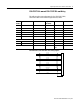
6 Right-angle Connection for Series B 1326 Cables
1326-CPC1T-RAL-xxx and 1326-CPC1T-RBL-xxx Wiring
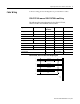
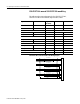
This table provides wiring information for the 1326-CPC1T-RAL,
1326-CPC1T-RBL motor feedback (high resolution) cables.
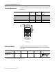
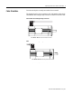
1326-CPC1T-RAL, 1326-CPC1T-RBL Cable Wiring Diagram
Wire
Number
Signal Wire Color Gauge
mm
2
(AWG)
Connector Pin 1394 Terminal
1 Power Black 2.59 (10) 1 U1
2 Power Black 2.59 (10) 2 V1
3 Power Black 2.59 (10) 3 W1
4 Brake Black 1.29 (16) 4 TB1-3
5 Thermostat Black 1.29 (16) 5 TB1-2
6 Brake Black 1.29 (16) 6 TB1-4
Overall shield Shield 2.05 (12) 7 PE3
8 GND Green/Yellow 2.05 (12) 8 PE2
9 Thermostat Black 1.29 (16) 9 TB1-1
Overall shield Braid N/A Connected to
shell
Ground stud
Shield
1
2
3
4
5
6
7
8
9
Wire #1
Wire #2
Wire #3
Wire #4
Wire #5
Wire #6
Green/Yellow
Wire #9