Bulletin 1336VT Adjustable Frequency AC Drive Programming Manual
Important User Information Because of the variety of uses for this equipment and because of the differences between this solid-state equipment and electromechanical equipment, the user of and those responsible for applying this equipment must satisfy themselves as to the acceptability of each application and use of the equipment. In no event will Allen-Bradley Company be responsible or liable for indirect or consequential damages resulting from the use or application of this equipment.
Table of Contents Local Parameter Programming . . . . . . . . . . . . . . . . . . . . . 1 1 At all Programming and Display Panels, parameters 0 50 and 70 89 may be viewed (Read) while the drive is running. Eight of these parameters display real time events (such as present drive speed and output current) that cannot be changed (Written to). The remaining parameters may be changed as long as the drive isn't running.
ii Table of Contents Local and Serial Port Parameters Firmware Version 1.01 3.01 . . . . . . . . . . . . . . . . . . . . . 3 1 Serial Port Parameters Firmware Version 1.01 3.01 . . . . . . . . . . . . . . . . . . . . . 4 1 Local and Serial Port Parameters Firmware Version 2.01 3.01 . . . . . . . . . . . . . . . . . . . . . 5 1 % Load/Current Conversion . . . . . . . . . . . . . . . . . . . . . . . . 7 1 % Power/kW Conversion . . . . . . . . . . . . . . . . . . . . . . . . . .
Preface Manual Objective The 1336VT Programming Manual is designed to be read and used like an ordinary textbook. Read the manual once from the beginning in the order presented to gain basic knowledge about your drive. Each chapter builds upon information presented in the previous chapter. Become familiar with tasks that must be performed in a sequence for safety and successful completion.
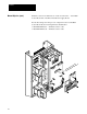
Preface Manual Objective (cont.) Firmware versions are marked at two locations in the drive – on the Main Control Board and on the Base Driver/Power Supply Board. For all drive ratings, the microprocessor chip U14 located on the Main Control Board has the following firmware identification: • P/N XXXXXXV1.01 –– Firmware Version 1.01. • P/N XXXXXXV1.10 –– Firmware Version 2.01. N ION ON UT AGENEO CA VOLTEN WERE US WH VE POFOR DO O AR ORS EM . BE HAZACIT ON. R SEC .
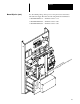
Preface Manual Objective (cont.) For 5-52 Amp ratings, microprocessor chip U21 located on the Base Driver/Power Supply Board has the following firmware identification: • P/N XXXXXXV1.01 –– Firmware Version 1.14. • P/N XXXXXXV1.11 –– Firmware Version 2.01. • P/N XXXXXXV3.01 –– Firmware Version 3.01. ly upp rd Boa U21 er S hip r/Pow C r e sso riv oce ase D r p B ro n Mic ted o a c Lo ION ON UT AGENEON CA VOLTN WER HE PO RE S OU W E FO RD RS MOV BE ZA HA CITOON. RESEC. G.
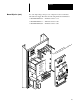
Preface Manual Objective (cont.) For 65-77 Amp ratings, microprocessor chip U2 located on the Base Driver/Power Supply Board has the following firmware identification: • P/N XXXXXXV1.14 –– Firmware Version 1.14. • P/N XXXXXXV2.01 –– Firmware Version 2.01. • P/N XXXXXXV3.01 –– Firmware Version 3.01.
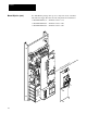
Preface For 96-180 Amp ratings, microprocessor chip U2 located on the Base Driver/Power Supply Board has the following firmware identification: • P/N XXXXXXV1.14 –– Firmware Version 1.14. • P/N XXXXXXV2.01 –– Firmware Version 2.01. • P/N XXXXXXV3.01 –– Firmware Version 3.01. D GN G M –– 6 AW 0 MC L3 E 35 NG E RA WIR UNDS PO UE RQ LY TO E ON NING WIR GHTE PPER TI °C CO E 75 275 INCH L2 L1 M3 M2 M1 US C –D C M – + M – +D + Manual Objective (cont.
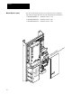
Preface Manual Objective (cont.) For 240-300 Amp ratings, microprocessor chip U2 located on the Base Driver/Power Supply Board has the following firmware identification: • P/N XXXXXXV1.14 –– Firmware Version 1.14. • P/N XXXXXXV2.01 –– Firmware Version 2.01. • P/N XXXXXXV3.01 –– Firmware Version 3.01. NLY. EO WIR G UNDS ER PP ) AW PO CO (3 CH °C ZE 2 5 IN E 75 SI 27 US WIRE RQUE D TO GN ING EN GHT TI L3 NLT.
Preface Manual Objective (cont.) This manual is meant to guide the user with interface, installation, setup and troubleshooting of a 1336VT. The contents are arranged in order from a general description to troubleshooting and maintenance. To assure successful installation and operation, the material presented must be thoroughly read and understood before proceeding. Particular attention must be directed to the Caution, Warning and Important statements contained within.
Chapter 1 Local Parameter Programming Programming and Display Panel Freq PR PR Enter Read and Write Restrictions At all Programming and Display Panels, parameters 0-50 and 70-89 may be viewed (Read) while the drive is running. Eight of these parameters display real-time events (such as present drive speed and output current) that cannot be changed (Written to). The remaining parameters may be changed as long as the drive isn’t running.
Chapter 1 Local Parameter Programming SW1 Operation SW1 is a rocker switch only accessible on the chassis mounted Local Programming and Display Panel. The switch can be accessed only with the drive cover removed and may be used to disable the Enter pushbutton and control access to local programming. Enter C1 ➁ 1 SW Enter button enabled — Access to programming allowed if SW1 is set to position C1.
Chapter 2 Serial Port Parameter Programming Read and Write Restrictions Serial Port parameter programming may be accomplished by using the 1336-MOD-E1 or 1336-MOD-G2 through the 1336-MOD-S1 Serial Port Connector. Through the Serial Port Connector, all parameters may be viewed (Read) while the drive is running. Eight of these parameters display real-time events (such as present drive speed and output current) that cannot be changed (Written to).
Chapter 3 Local and Serial Port Parameters Firmware Version 1.01 3.01 The 1336VT drive logic uses a set of 90 user parameters to select and control drive operation. Seventy-one of these parameters are accessible through any of the Programming and Display Panels. All 90 are accessible through the Serial Port. Initial values for each parameter have been preset at the factory and are shown in the following displays.
Chapter 3 Local and Serial Port Parameters Firmware Version 1.01-3.01 Parameter 1 -- Output Volts Freq Read Only Units PR Minimum Value Maximum Value Factory Setting PR Volts 0 575 0 Enter When this parameter is selected for viewing, the drive output voltage can be viewed while the drive is running.
Chapter 3 Local and Serial Port Parameters Firmware Version 1.01-3.01 Parameter 3 Output Power Freq Read Only Units PR Minimum Value Maximum Value Factory Setting PR % of Rated Output Power Enter 0 200 0 When this parameter is selected for viewing, the output power of the drive as a % of rated output power can be viewed while the drive is running. Refer to the % Power/HP Conversion Tables in Chapter 8, or the % Power/kW Conversion Tables in Chapter 9 for quick conversions.
Chapter 3 Local and Serial Port Parameters Firmware Version 1.01-3.01 Parameter 5 Frequency Select 1 Freq Read and Write Units PR Minimum Value Maximum Value Factory Setting PR Code 0 5 0 Enter This parameter selects one of six possible sources to control drive output frequency when TB3 Terminal 27 is false.
Chapter 3 Local and Serial Port Parameters Firmware Version 1.01-3.01 Parameter 6 Frequency Select 2 Freq Read and Write Units PR Minimum Value Maximum Value Factory Setting PR Code 0 5 0 Enter This parameter selects one of six possible sources to control the drive output frequency when Terminal 27 at TB3 is true.
Chapter 3 Local and Serial Port Parameters Firmware Version 1.01-3.01 Parameter 7 Accel Time 1 Freq Read and Write Units PR Minimum Value Maximum Value Factory Setting PR Seconds 0 600 5 Enter This parameter determines the time that it will take the drive to ramp from 0 Hz to the maximum frequency programmed into Parameter 19.
Chapter 3 Local and Serial Port Parameters Firmware Version 1.01-3.01 Parameter 9 DC Boost Select Freq Read and Write Units PR Minimum Value Maximum Value Factory Setting PR Code 0 12 2 Enter This parameter provides a selectable DC boost voltage to the motor at low drive frequency to allow the drive/motor combination to be adapted to various starting torque conditions. Usually increased starting torque requires more DC boost.
Chapter 3 Local and Serial Port Parameters Firmware Version 1.01-3.01 Parameter 10 -- Stop Select Freq PR Read and Write Units PR Minimum Value Maximum Value Factory Setting Code 0 2 0 Enter This parameter selects the stopping performance of the motor. Zero (0) = coast-to-stop. The drive will shut off output frequency on receiving a Stop command to allow the motor to coast-to-stop. Set Parameter 12 to 0 seconds and Parameter 13 to 0 volts when Parameter 10 is set to 0. One (1) = DC brake-to-stop.
Chapter 3 Local and Serial Port Parameters Firmware Version 1.01-3.01 Parameter 11 Decel Frequency Hold Freq Read and Write Units PR Minimum Value Maximum Value Factory Setting PR Off/On 0 1 0 Enter This parameter may be used to guard against overvoltage fault trips from occurring due to fast decel ramps. The status of this parameter selects the drive response to a condition where the DC bus level is rising towards the overvoltage trip point.
Chapter 3 Local and Serial Port Parameters Firmware Version 1.01-3.01 Parameter 12 DC Hold Time Freq Read and Write Units PR Minimum Value Maximum Value Factory Setting PR Seconds 0 15 0 Enter The time represented by this value affects drive stopping performance. Parameter 10 determines how this parameter value is used. When Parameter 10 is set to 0, Parameters 12 and 13 should also be set to 0.
Chapter 3 Local and Serial Port Parameters Firmware Version 1.01-3.01 Parameter 13 DC Hold Volts Freq PR Read and Write Units PR Minimum Value Maximum Value Factory Setting Volts 0 115 0 Enter The value of this parameter sets the DC Hold Voltage that is applied to the motor during the DC Hold Time set by Parameter 12. The optimum setting for this parameter is a function of external variables — motor size, load inertia, friction load and other factors.
Chapter 3 Local and Serial Port Parameters Firmware Version 1.01-3.01 Parameter 14 Auto Restart Freq PR Read and Write Units PR Minimum Value Maximum Value Factory Setting Off/On 0 1 1 Enter Auto Restart along with Parameters 40 and 85, affects the drive restart sequence after a line loss condition. Parameter 40 allows the sensing of a line power interrupt condition. Parameter 85 sets the number of times the drive will attempt to restart after a fault.
Chapter 3 Local and Serial Port Parameters Firmware Version 1.01-3.01 Parameter 15 Factory Set Freq Read and Write Units PR Minimum Value Maximum Value Factory Setting PR None 0 0 0 Enter This parameter may be viewed but should not be changed from its factory setting. Parameter 16 Minimum Frequency Freq Read and Write Units PR Minimum Value Maximum Value Factory Setting PR Hertz 0 120 0 Enter This parameter sets the minimum drive operating frequency.
Chapter 3 Local and Serial Port Parameters Firmware Version 1.01-3.01 Parameter 17 Base Frequency Freq Read and Write Units PR Minimum Value Maximum Value Factory Setting PR Hertz 40 120 60 Enter Parameters 17 and 18 are typically set to the nameplate values of the connected motor. Parameter 17 in conjunction with Parameter 18 and the addition of DC Boost Select set by Parameters 9, 48, 49 and 50, determines the drive output volts-per-hertz slope up to Base Frequency.
Chapter 3 Local and Serial Port Parameters Firmware Version 1.01-3.01 Parameter 19 Maximum Frequency Freq PR Read and Write Units PR Minimum Value Maximum Value Factory Setting Hertz 40 250 60 Enter This parameter sets the highest frequency that the drive will produce when given a maximum speed command. The drive reaches this speed when a local or remote potentiometer or a digital speed command is at its maximum level unless Parameter 84 is set to 1. That is: • A +10V DC input at its maximum level.
Chapter 3 Local and Serial Port Parameters Firmware Version 1.01-3.01 Parameter 20 Maximum Volts Freq Read and Write Units PR Minimum Value Maximum Value Factory Setting PR Volts 115 575 460 Enter This parameter sets the maximum RMS output voltage of the drive. It may also be used to set the volts-per-hertz curve when the drive is operating between Base Frequency and Maximum Frequency.
Chapter 3 Local and Serial Port Parameters Firmware Version 1.01-3.01 Parameter 22 Local Reverse Freq Read and Write Units PR Minimum Value Maximum Value Factory Setting PR Off/On 0 1 1 Enter Parameter 22 selects the source that determines the direction of motor rotation. When set to 0, the direction of rotation is controlled by either the status of the reverse input at TB3 or through serial communications.
Chapter 3 Local and Serial Port Parameters Firmware Version 1.01-3.01 Parameter 24 Jog Frequency Freq Read and Write Units PR Minimum Value Maximum Value Factory Setting PR Hertz .0 120 .0 Enter The value of this parameter is the speed reference frequency used when jog is commanded. Any time jog is commanded, the drive will ramp to this frequency. Upon removing the jog command, if no other motion command is present, the drive will follow the stopping mode selected in Parameter 10.
Chapter 3 Local and Serial Port Parameters Firmware Version 1.01-3.01 Parameter 26 Preset/2nd Accel Freq PR Read and Write Units PR Minimum Value Maximum Value Factory Setting Code 0 1 0 Enter This parameter selects which drive function will be controlled by optional inputs SW1, SW2, Speed Select at terminal block TB3 and Parameter 72, Activate Parameters 73-76.
Chapter 3 Local and Serial Port Parameters Firmware Version 1.01-3.01 Parameter 26 3-20 Preset/2nd Accel If Parameter 26 is set to 1, SW1, SW2, Speed Select and Parameter 72 will (cont.
Chapter 3 Local and Serial Port Parameters Firmware Version 1.01-3.01 Parameter 27 Preset Frequency 1 Freq Read and Write Units PR Minimum Value Maximum Value Factory Setting PR Hertz .0 250 .0 Enter The value of this parameter is the command frequency when Preset Frequency 1 is selected. Parameter 28 Preset Frequency 2 Freq Read and Write Units PR Minimum Value Maximum Value Factory Setting PR Hertz .0 250 .
Chapter 3 Local and Serial Port Parameters Firmware Version 1.01-3.01 Parameter 30 Accel Time 2 Freq Read and Write Units PR Minimum Value Maximum Value Factory Setting PR Seconds 0 600 5 Enter The value of this parameter is the time in seconds it will take the drive frequency to ramp from zero to the Maximum Frequency set by Parameter 19 when Accel Time 2 is selected.
Chapter 3 Local and Serial Port Parameters Firmware Version 1.01-3.01 Parameters 32 35 Parameter 32 Parameters 32 – 35 may be used to program up to three Skip Frequency Bands. Each band establishes a range of frequencies at which the drive will not operate. If the frequency source that is presently controlling the drive is within the band, the drive output frequency will stay slightly above or below the band until the frequency source changes to a frequency outside the band.
Chapter 3 Local and Serial Port Parameters Firmware Version 1.01-3.01 Parameter 35 Skip Frequency Band Freq Read and Write Units PR Minimum Value Maximum Value Factory Setting PR Hertz 0 15 0 Enter Parameter 35 is programmed for the Skip Frequency Band — the range of frequencies to skip. It is used for each of the skip frequency ranges programmed.
Chapter 3 Local and Serial Port Parameters Firmware Version 1.01-3.01 Parameter 36 MOPC Freq Read and Write Units PR Minimum Value Maximum Value Factory Setting PR % of Rated Output Current Enter 50 115 115 Important: Overload Current (Parameter 38) limits the drive output current independent of the setting of Parameter 36. The overload range available from the drive will be limited by the lower of the two settings.
Chapter 3 Local and Serial Port Parameters Firmware Version 1.01-3.01 Parameter 37 Serial Baud Rate Freq Read and Write Units PR Minimum Value Maximum Value Factory Setting PR Code 0 1 1 Enter This parameter allows the baud rate for communicating with remote serial devices to be set to either 9600 (0) or 2400 (1) baud. Each time Parameter 37 is changed, power must be recycled to the drive before the new baud rate can be used.
Chapter 3 Local and Serial Port Parameters Firmware Version 1.01-3.01 Parameter 38 Overload Current Freq Read and Write Units PR Minimum Value Maximum Value Factory Setting PR % of Rated Output Current Enter 50 115 100 Important: MOPC Parameter 36 limits the drive output current independent of the setting of Parameter 38. The overload range available from the drive will be limited by the lower of the two settings.
Chapter 3 Local and Serial Port Parameters Firmware Version 1.01-3.01 Parameter 39 Fault Clear Freq Read and Write Units PR Minimum Value Maximum Value Factory Setting PR Off/On 0 1 1 Enter This parameter determines the sequence of events required to clear a Fault Code at the drive. The setting of Parameter 14, Auto Restart, will affect the sequence required to reset the drive after a fault has occurred.
Chapter 3 Local and Serial Port Parameters Firmware Version 1.01-3.01 Parameter 40 Power Fault Freq Read and Write Units PR Minimum Value Maximum Value Factory Setting PR On/Off 0 1 0 Enter This parameter allows the sensing of a line power interrupt condition. If set to 1, only the following sequence can occur. On interruption of input power to the drive, the drive will continue to operate from the stored energy of the DC bus until bus voltage drops below 85% of its nominal value.
Chapter 3 Local and Serial Port Parameters Firmware Version 1.01-3.01 Parameter 41 Motor Type Freq Read and Write Units PR Minimum Value Maximum Value Factory Setting PR Code 0 2 0 Enter Parameter 41 allows one of three motor types to be selected for drive control: • Induction by setting Parameter 41 to 0. • Synchronous reluctance by setting Parameter 41 to 1. • Synchronous Permanent Magnet by setting Parameter 41 to 2.
Chapter 3 Local and Serial Port Parameters Firmware Version 1.01-3.01 Parameter 42 Slip Compensation Freq Read and Write Units PR Minimum Value Maximum Value Factory Setting PR Hertz .0 5.0 .0 Enter Important: Parameter 78, Traverse Period, must be set to 0 to allow Slip Compensation. If not, the drive will fault and display F37 –– P-Jump Error. Parameter 42 adds frequency to the drive output.
Chapter 3 Local and Serial Port Parameters Firmware Version 1.01-3.01 Parameter 42 Slip Compensation (cont.) An “at speed” circuit in the drive monitors drive output frequency. As long as the input speed reference to the drive remains constant, the hertz set by Parameter 42 will be proportionally added to the drive output frequency. If the speed command to the drive is increased or decreased, slip compensation will not be added until the command speed matches the drive output frequency.
Chapter 3 Local and Serial Port Parameters Firmware Version 1.01-3.01 Parameter 44 Dwell Time Freq Read and Write Units PR Minimum Value Maximum Value Factory Setting PR Seconds 0 10 0 Enter This function sets the time in seconds the drive will hold at the dwell frequency, Parameter 43. Parameter 45 PWM Frequency Freq Read and Write Units PR Minimum Value Maximum Value Factory Setting PR kHz .40 2.00 .
Chapter 3 Local and Serial Port Parameters Firmware Version 1.01-3.01 Parameter 46 Pulse Scale Factor Freq Read and Write Units PR Minimum Value Maximum Value Factory Setting PR Ratio 1 255 64 Enter This parameter establishes the input pulse ratio required to produce a proportional output command frequency when the pulse train input is selected. The command frequency is determined by dividing the pulse train frequency by the value set by Parameter 46.
Chapter 3 Local and Serial Port Parameters Firmware Version 1.01-3.01 Parameters 48 50 Important: Parameters 48-50 may be used to program a custom volts-per-hertz curve for the 1336VT for special motor applications.
Chapter 3 Local and Serial Port Parameters Firmware Version 1.01-3.01 Parameter 49 Break Frequency Freq Read and Write Units PR Minimum Value Maximum Value Factory Setting PR Hertz 0 120 0 Enter This parameter sets an intermediate frequency below Parameter 17 (Base Frequency), if Parameter 9 is set to 11. This parameter along with Parameters 48 and 50 are used to construct a custom volts-per-hertz curve.
Chapter 4 Serial Port Parameters Firmware Version 1.01 3.01 Parameters 51-69 may only be accessed through options connected to the serial port connector, not through a Programming and Display Panel. For a description of serial port options that use the serial interface, reference the individual option instructions — 1336-MOD-E1, 1336-MOD-E2 and 1336-MOD-G2. Initial values for each parameter have been preset at the factory and are listed in the following descriptions.
Chapter 4 Serial Port Parameters Firmware Version 1.01-3.01 Parameter 54 Local Input Read Only Units Min Value Max Value Byte 0 255 This parameter is an eight-bit word that reports the status of the pushbuttons on an optional Control or Programming and Display Panel. BIT 0 Stop BIT 1 Start BIT 2 Jog BIT 3 BIT 4 Enter BIT 5 PR BIT 6 BIT 7 0 = Off (not pressed) Parameter 55 Remote Input Read Only Units Min Value Max Value 1 = On (pressed) Byte 0 255 This parameter is an eight-bit word.
Chapter 4 Serial Port Parameters Firmware Version 1.01-3.01 Parameter 56 Serial Input Read Only Units Min Value Max Value Byte 0 255 This parameter is the drive storage location for the Serial Input byte. This same byte is used to control the drive through the PLC Controller Output Image Table. This parameter is an eight-bit word where each bit represents the following parameter or control function. The Serial Mask Parameter 57, controls whether these bits are used by the drive.
Chapter 4 Serial Port Parameters Firmware Version 1.01-3.01 Parameter 56 Serial Input (cont.) BIT 4 — Jog — 0 = select (not) Jog — continue last state 1 = select Jog at Jog Frequency, Parameter 24 BIT 5 — Direction — 0 = select Forward 1 = select Reverse BIT 6 — Stop — 0 = select Stop 1 = select (not) Stop — continue last state BIT 7 — Start — 0 = select (not) Start — continue last state 1 = select Start ! ATTENTION: Unexpected machine motion can cause injury or death.
Chapter 4 Serial Port Parameters Firmware Version 1.01-3.01 Parameter 57 Serial Mask Read and Write Units Min Value Max Value Factory Setting Byte 0 255 0 This parameter permits the masking of any one of the bits defined in Parameter 56. Each bit in this parameter must be set to 1 to allow the corresponding bit in Parameter 56 to be fully functional. Important: If power is removed from the drive, a default state will occur resetting all bits in Parameter 57 to 0.
Chapter 4 Serial Port Parameters Firmware Version 1.01-3.01 Parameter 57 4-6 Serial Mask (cont.) BIT 4 — Jog — 0 = drive will not accept Jog command bit 1 = Jog at Jog Frequency, Parameter 24, may be selected. BIT 5 — Direction — 0 = drive will not accept Direction command bit. 1 = direction change allowed. BIT 6 — Stop — 0 = data will not stop drive. 1 = data will stop drive. BIT 7 — Start — 0 = data will not start drive. 1 = data will start drive.
Chapter 4 Serial Port Parameters Firmware Version 1.01-3.01 Parameter 58 Drive Command Read Only Units Min Value Max Value Byte 0 255 This parameter represents the status of various inputs that control the drive. It is an eight-bit word but only five bits contain actual status information.
Chapter 4 Serial Port Parameters Firmware Version 1.01-3.01 Parameter 59 Drive Status Read Only Units Min Value Max Value Byte 0 255 This parameter is an eight-bit word that corresponds to the status byte read by the PLC Controller input image table. It reports the actual operating status of the drive.
Chapter 4 Serial Port Parameters Firmware Version 1.01-3.01 Parameter 60 Drive Alarm Read Only Units Min Value Max Value Byte 0 255 This parameter is an eight-bit word that shows the status of the six possible drive alarm conditions.
Chapter 4 Serial Port Parameters Firmware Version 1.01-3.01 Parameter 61 Drive Type Read Only Units Min Value Max Value Byte 0 255 This parameter is an eight bit word that indicates the voltage and power rating of the drive.
Chapter 4 Serial Port Parameters Firmware Version 1.01-3.01 Parameter 62 Frequency Source Read Only Units Min Value Max Value Code 0 13 This parameter reports to the drive which frequency source is currently being used to command the drive.
Chapter 4 Serial Port Parameters Firmware Version 1.01-3.01 Parameter 65 Command Frequency Read Only Units Min Value Max Value Hertz 0.00 250.00 This parameter represents the present drive command frequency set by the current command source. The current command source will be indicated by a code from 0-9 and shown by selecting Parameters 5 or 6. Parameter 66 Output Frequency Read Only Units Min Value Max Value Hertz 0.00 250.
Chapter 4 Serial Port Parameters Firmware Version 1.01-3.01 This parameter serves as a memory location for the direction of drive rotation as controlled by the Local Control Panel.
Chapter 5 Local and Serial Port Parameters Firmware Version 2.01 3.01 The remaining parameters — from 70 on up — are local and serial port parameters that may only be accessed with Firmware Version 2.01-3.01. Initial values for each parameter have been preset at the factory and are listed in the following descriptions. Any interaction or preconditions required for setting parameters are also included in the following descriptions.
Chapter 5 Local and Serial Port Parameters Firmware Version 2.01-3.01 Parameter 72 -- Activate Parameters 73 76 Freq Read and Write Units PR Minimum Value Maximum Value Factory Setting PR Off/On 0 1 0 Enter If set to 1, this parameter will allow Preset Frequencies 73-76 to be used. Individual preset frequencies are selected by the setting of switches SW1 and SW2, and the Speed Select input at terminal block TB3 of the drive.
Chapter 5 Local and Serial Port Parameters Firmware Version 2.01-3.01 Parameter 75 -- Preset Frequency 6 Freq Read and Write Units PR Minimum Value Maximum Value Factory Setting PR Hertz .0 250 .0 Enter The value of this parameter is the command frequency when Preset Frequency 6 is selected. Parameter 76 -- Preset Frequency 7 Freq Read and Write Units PR Minimum Value Maximum Value Factory Setting PR Hertz .0 250 .
Chapter 5 Local and Serial Port Parameters Firmware Version 2.01-3.01 Parameter 77 -- Above Frequency Contact Freq Read and Write Units PR Minimum Value Maximum Value Factory Setting PR Hertz 0 250 0 Enter This parameter works in conjunction with terminals 10 and 11 of drive terminal block TB2. Terminals 10 and 11 allow an internal drive supplied at speed contact to be used in external circuits. The N.O. contact closes when the drive’s output frequency reaches the command speed within ±0.
Chapter 5 Local and Serial Port Parameters Firmware Version 2.01-3.01 Parameter 78 -- Traverse Period Freq Read and Write Units PR Minimum Value Maximum Value Factory Setting PR Seconds 0 30 0 Enter This parameter is not typically used in variable torque applications and should not be changed from its factory setting. Parameter 79 -- Maximum Traverse Freq Read and Write Units PR Minimum Value Maximum Value Factory Setting PR Hertz .0 100 .
Chapter 5 Local and Serial Port Parameters Firmware Version 2.01-3.01 Parameter 81 -- Soft Start/Stop Enable Freq Read and Write Units PR Minimum Value Maximum Value Factory Setting PR Off/On 0 1 0 Enter This parameter is currently not implemented.
Chapter 5 Local and Serial Port Parameters Firmware Version 2.01-3.01 Parameter 83 -- Run Boost Freq PR Read and Write Units PR Minimum Value Maximum Value Factory Setting Volts 0 115 0 Enter Important: If Run Boost is greater than Start Boost (Parameter 48), the drive will fault and display F34 –– Boost Error.
Chapter 5 Local and Serial Port Parameters Firmware Version 2.01-3.01 Parameter 84 -- Analog Inverse Freq PR Read and Write Units PR Minimum Value Maximum Value Factory Setting Off/On 0 1 0 Enter When this parameter is set to 0 (disabled), the 0-10V DC and 4-20mA analog inputs at terminal block TB2 in the drive will function as described in the User Manual.
Chapter 5 Local and Serial Port Parameters Firmware Version 2.01-3.01 Parameter 85 -- Restart Tries Freq Read and Write Units PR Minimum Value Maximum Value Factory Setting PR Code 0 9 0 Enter Important: Parameters 14 and 85 require two-wire control to allow an auto restart sequence to occur. 1336VT two-wire control requires that Logic Interface Option L1, L2 or L3 be installed in the drive.
Chapter 5 Local and Serial Port Parameters Firmware Version 2.01-3.01 Parameters 86 89 Parameters 86-89 will store the last (4) faults that the drive has encountered. These buffers will be implemented in a cascading mode, that is when a different fault occurs, the following sequence will take place. • Fault Buffer 0 will store the new fault. • Fault Buffer 1 will store the fault from Fault Buffer 0. • Fault Buffer 2 will store the fault from Fault Buffer 1.
Chapter 5 Local and Serial Port Parameters Firmware Version 2.01-3.
Chapter 6 Overload Current Settings Table 6 -- Overload Current Settings for 1336VT Drives Example:Drive rating = B003 Approximate Motor Full Load Current Rating = 3.
Chapter 6 Overload Current Settings Table 6 -- Overload Current Settings for 1336VT Drives Parameter 38 Setting B003 B005 B007 B010 B015 B020 MOTOR FULL LOAD CURRENT RATING B025 B030 B040 B050 B060 B075 B100 B125 B150 B200 B250 50 51 52 53 54 2.50 2.55 2.60 2.65 2.70 4.00 4.08 4.16 4.24 4.32 5.50 5.61 5.72 5.83 5.94 7.00 7.14 7.28 7.42 7.56 10.5 10.7 10.9 11.1 11.3 13.5 13.8 14.0 14.3 14.6 17.0 17.3 17.7 18.0 18.4 20.0 20.4 20.8 21.2 21.6 26.0 26.5 27.0 27.6 28.1 32.5 33.2 33.8 34.
Chapter 7 % Load/Current Conversion Table 7 -- % Load/Current Conversion for 1336VT Drives Example:Parameter 2 = 52 Drive rating = B003 Rated Power = 52% = 50% + 2% = 2.5 + 0.1 = 2.6 Amps % B003 B005 B007 B010 B015 B020 B025 B030 B040 B050 B060 B075 B100 B125 B150 B200 B250 1 2 3 4 5 0.1 0.1 0.2 0.2 0.3 0.1 0.2 0.2 0.3 0.4 0.1 0.2 0.3 0.4 0.6 0.1 0.3 0.4 0.6 0.7 0.2 0.4 0.6 0.8 1.1 0.3 0.5 0.8 1.1 1.4 0.3 0.7 1.0 1.4 1.7 0.4 0.8 1.2 1.6 2.0 0.5 1.0 1.6 2.1 2.6 0.7 1.3 2.0 2.
Chapter 8 % Power/kW Conversion Table 8 -- % Power/kW Conversion for 1336VT Drives Example:Parameter 3 = 36 Drive rating = B005 Rated Power = 36% = 30% + 6% = 1.1 + 0.2 = 1.3 kW % B003 B005 B007 B010 B015 B020 B025 B030 B040 B050 B060 B075 B100 B125 B150 B200 B250 1 2 3 4 5 0.02 0.04 0.07 0.09 0.11 0.04 0.07 0.11 0.15 0.19 0.06 0.11 0.17 0.22 0.28 0.07 0.15 0.22 0.30 0.37 0.11 0.22 0.34 0.45 0.56 0.15 0.30 0.45 0.60 0.75 0.19 0.37 0.56 0.75 0.93 0.22 0.45 0.67 0.90 1.12 0.30 0.
Chapter 9 Local and Serial Port Parameter Settings Firmware Version 1.01 3.01 Table 9 -- Parameter List for Parameters 0 to 50 Parameters 0 to 50 can be accessed through either the local or serial port.
Chapter 9 Local and Serial Port Parameter Settings Firmware Version 1.01-3.01 Table 9 -- Parameter List for Parameters 0 to 50 (cont.) Parameter Parameter Number Text 9-2 Units Local Programming Panel Min/Max Values Serial Port Min/Max Values Factory Setting Seconds Seconds Hertz Hertz Hertz 0/600 0/600 0/250 0/250 0/250 0.00/600.00 0.00/600.
Chapter 10 Serial Port Parameter Settings Firmware Version 1.01 3.01 Table 10 -- Parameter List for Parameters 51 to 69 Parameters 51 to 69 can be accessed only through the serial port.
Chapter 11 Local and Serial Port Parameter Settings Firmware Version 2.01 and 3.01 Table 11 -- Parameter List for Parameters 70 to 89 Parameters 70 to 89 are local and serial port parameters that may only be accessed with Firmware Version 2.01 and 3.01.
Appendix A Start and Run Boost Settings The following setup procedure may be used to maximize starting torque and minimize motor heating. The procedure is written for users who have the optional Handheld Terminal (HHT) or a Control Panel installed, and who are not using a 2-wire drive control scheme. For users without the optional HHT or Control Panel, respective external commands and signals must be substituted to simulate the operation of the HHT or a Control Panel.
Appendix A Start and Run Boost Settings DC Boost Usually increased starting torque requires more DC boost. High boost may produce unnecessary current at low frequency and contribute to motor overheating. Excessive boost may force the drive into MOPC resulting in poor drive performance. The optimum DC boost is the lowest level that will permit satisfactory starting torque in a properly sized motor and drive application.
Appendix A Start and Run Boost Settings Procedure (cont.) 100% Drive Output Current 75% Drive Output Current 50% Drive Output Current 25% Drive Output Current Parameter 9 = 2 DC Boost = 0V 3 4 5 6 7 8 9 10 6V 12V 18V 24V 30V 36V 42V 48V 3. Once smooth acceleration is obtained, set DC boost (Parameter 9) to 2, then 3, 4, 5, 6, 7, 8, 9 and finally 10. Monitor and record drive output current (Parameter 2) at each setting in the graph above.
Appendix A Start and Run Boost Settings Procedure (cont.) 4. Stop the drive and set drive frequency to the highest operating point required by the application (typically 60 Hz). 5. Construct a custom start and run DC boost curve by setting Parameter 9 to 12. • Set start boost (Parameter 48) to a value that will be 3 volts greater than the DC boost set in step 3. • Set run boost (Parameter 83) to 2/3 of the value of Parameter 48. 6. Start the drive.
Publication 1336VT-5.1 January, 1994 Supersedes June, 1993 P/N 155111 Copyright 1994, Allen Bradley Company, Inc.