Bulletin 1395 ControlNetTM Communication Board Firmware Rev 1.01 Compatible with ControlNet Version 1.
Important User Information Solid state equipment has operational characteristics differing from those of electromechanical equipment. “Safety Guidelines for the Application, Installation and Maintenance of Solid State Controls” (Publication SGI-1.1 available from your local Allen-Bradley Sales Office or online at http:// www.ab.com/manuals/gi) describes some important differences between solid state equipment and hard-wired electromechanical devices.
Table of Contents Before You Begin Chapter 1 Objective . . . . . . . . . . . . . . . . . . . . . . . . . . . . . . . . . . . . . . . . . . Audience . . . . . . . . . . . . . . . . . . . . . . . . . . . . . . . . . . . . . . . . . . Term Useage . . . . . . . . . . . . . . . . . . . . . . . . . . . . . . . . . . . . . . . . ControlNet Adapter Compatibility & Features . . . . . . . . . . . . . . . . . Safety Precautions . . . . . . . . . . . . . . . . . . . . . . . . . . . . . . . . . . . .
toc–ii Table of Contents Read Parameter Full . . . . . . . . . . . . . . . . . . . . . . . . . . . . . . . . . . Write Parameter Data . . . . . . . . . . . . . . . . . . . . . . . . . . . . . . . . . Read System Clock . . . . . . . . . . . . . . . . . . . . . . . . . . . . . . . . . . . Write System Clock . . . . . . . . . . . . . . . . . . . . . . . . . . . . . . . . . . . Drive System Reset . . . . . . . . . . . . . . . . . . . . . . . . . . . . . . . . . . . Clear Faults . . . . . . . . . . . . . . . .
Table of Contents Periodic Maintenance Chapter 7 Preventative Maintenance . . . . . . . . . . . . . . . . . . . . . . . . . . . . . . Tests & Records . . . . . . . . . . . . . . . . . . . . . . . . . . . . . . . . . . . . . Reference toc–iii 7-1 7-2 Chapter 8 Chapter Objective . . . . . . . . . . . . . . . . . . . . . . . . . . . . . . . . . . . . Terminology . . . . . . . . . . . . . . . . . . . . . . . . . . . . . . . . . . . . . . . . Detailed Parameter Listing . . . . . . . . . . . . . . . . . . .
toc–iv Table of Contents This Page Intentionally Blank Publication 1395–5.
Chapter 1 Before You Begin Objective This manual contains the information necessary to perform the following functions on the ControlNet Adapter (CNA) Board: S Install and Set-up the CNA board S Configure the Drive for control by a PLC Controller S Maintain and Troubleshoot the board Audience This manual is intended for use by expert personnel familiar with the functions of solid state drive equipment.
1–2 Before You Begin Safety Precautions The following types of precautionary statements will be found in this manual. IMPORTANT: Identifies particular areas of concern for correct board, processor or Drive operation. ! ! Manual Organization ATTENTION: Identifies information about practices or circumstances that can lead to personal injury or death, property damage, or economic loss. ATTENTION: This board contains ESD (electostatic discharge) sensitive parts and assemblies.
Before You Begin Specifications Electrical: Board power provided by Drive Environmental: Ambient Operating Temperature Storage Temperature Relative Humidity Firmware Version 1–3 24VDC or 115VAC 0° to 60°C (32° to 140°F) –40° to +85°C (–40° to +185°F) 5% to 95% non-condensing 1.xx Publication 1395.5.
1–4 Before You Begin This Page Intentionally Blank Publication 1395.5.
Chapter 2 Introduction & Product Description Chapter Objective This chapter contains a description of the major hardware components of the ControlNet Adapter board. It is not intended to be an all encompassing technical description of each hardware component. This chapter provides information to aid service personnel in: S Identifing the CNA board. S Understanding the hardware content of the board. S Understanding the hardware requirements necessary to interface this board with external devices.
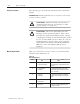
2–2 Introduction & Product Description faulted or not faulted. LED’s DS2 and DS3 duplicate the function provided by the LED’s on the Interface Plug. LED DS4 is inactive in this application. Tables 2.A and 2.B provide information on LED’s DS1-DS3. Table 2.A. LED Indicator Status for Board LED CNA Board Status State Function DS1 LED Green – Blinking at 1 Hz LED Green – Blinking Rapidly LED Off Normal Adapter Operation Adapter is Faulted Adapter Non-Operational Table 2.B.
2–3 Figure 2.1. CNA Board Components J1 U6 Firmware UMAI U20 CA STS DS1 Channel A STS DS2 Channel B STS DS3 Interface Plug R T Primary Channel 1 2 3 R T Redundant Channel Network Access Port ËË ËË ËË ËË ËË ËË 4 J5 TE Bus Publication 1395–5.
2–4 DIP Switch Orientation DIP Switch orientation (Figure 2.2) on the CNA board is as Follows: CLOSED = “ON” = “1” OPEN= “OFF” = “0” Figure 2.2. DIP Switch Orientation On Off On On Off Off Board Location The standard mounting position for the CNA board is Port B of the Drive (Refer to Figure 2.3). If required, the Adapter can be mounted in Port A. Note that each port uses different parameters to store Adapter setup and configuration information. Figure 2.3.
Chapter 3 Configuration & PLC Interfacing Chapter Objective This chapter contains a general description of the CNA Board’s features and functions. It is intended to provide background information to support other procedures in this manual and help you to: S Configure the Drive for use with the ControlNet Adapter Board S Interface the Drive with an Allen-Bradley PLC Controller. This chapter is not intended to be an all encompassing technical description of the CNA Board.
3–2 Configuration & PLC Interfacing Parameter Table – A table which contains all parameters that are available in the Drive and adapters. Source Parameter – A parameter that contains real time information that is available for use by other devices. These devices can include PLC controllers, operator interface devices, program terminals, etc. Sink Parameter – Sink parameters accept data from other parameters which is then used by the Drive to perform the desired functions.
Configuration & PLC Interfacing 3–3 Figure 3.1 presents an overview of the CNA board with a typical Channel configuration. The parameter numbers shown are for a CNA board mounted in Port B of the Drive. This is the standard Port for the CNA Board. Figure 3.1.
3–4 Configuration & PLC Interfacing General The CNA board does not scale or manipulate data that is transferred between the Drive and PLC Controller. If data in the PLC is manipulated in units other than Drive units, the data must first be converted to Drive Units before being sent to the Drive. Consequently, all scaling of data must be performed in the PLC. To control Drive parameters the CNA parameters are linked to the Drive by using source and sink parameters.
Configuration & PLC Interfacing 3–5 Figure 3.3. ControlNet Adapter Configuration Example PLC Controller Output Image Table CNA Board Bulletin 1395 Drive Input Variables Group Number Full 0 1 2 3 4 5 6 7 Port B 300 301 302 303 304 305 306 307 1 2 User Configurable Soft Links 3 4 5 6 7 8 Input Image Table Output Variables Group Number Full 0 1 2 3 4 5 6 7 Port B 350 1 351 352 353 354 355 356 2 357 3 4 5 User Configurable Soft Links 6 7 8 Publication 1395–5.
3–6 Configuration & PLC Interfacing Discrete PLC Controller I/O Example Figure 3.4 illustrates an application where the 6 bit words for group 1 and 2 are being used by the PLC Controller program for data transfer with the Drive. In this example, the Drive has been configured so that the data coming into source parameter 300 is sent to Logic Cmd 1 (parameter 150).
Configuration & PLC Interfacing 3–7 integer whose value corresponds to the allowable values in Drive Units for parameter 106. If the data transferred between the Drive and PLC Controller will be manipulated (in the PLC Controller) in units other than Drive Units, the PLC Controller program must scale the information. The scaled information must be based on the Drive Units definitions for the parameters in the Drive.
3–8 Configuration & PLC Interfacing Figure 3.5.
Configuration & PLC Interfacing 3–9 Bit numbering in the PLC Controller is performed in Octal, as opposed to Decimal numbering in the Drive parameter 150, so it is necessary to relate the output image table bits to the controlled bits in parameter 150. Figure 3.6 shows the correlation between the output image table bits and the Drive parameter 150 bits.
3–10 Configuration & PLC Interfacing is used to store the speed reference for the Drive. The MOV block in rung 6 of Figure 3.5 transfers the 16 bit word of N10:01 to word 2 of the output image table. Because word 2 of the output image table is sent to parameter 301, which in turn is linked to parameter 154 (Figure 3.4), the 16 bit word N10:01 is the speed reference input to the Drive param. 154.
Configuration & PLC Interfacing 3–11 PLC Typed Read (N30:0-999) - This request translates into a read parameter full message in the Drive. Each parameter specified results in 13 words of data (actual value, minimum value, maximum value, descriptor, and parameter text). You can read a maximum of 5 parameters with this service. PLC Typed Read (N40:0-39) - This message emulates the RIO block transfer functions available on the CNA board with the exception of the multiple parameter read.
3–12 Configuration & PLC Interfacing Publication 1395–5.
Configuration & PLC Interfacing Upload Configuration Link 3–13 This function uploads the configuration table information from the Drive in blocks. Each block of configuration data has a separate function code.
3–14 Configuration & PLC Interfacing Download Configuration Link This function downloads the configuration table information from the Drive in blocks. Each block of configuration data has a separate function code.
Configuration & PLC Interfacing 3–15 IMPORTANT: Drive configuration links will not be changed by the Drive unless the following two conditions are met: 1. The Drive must not be running (i.e. the DC loop contactor must not be energized). 2. The Drive receives the fifth block (function code 2564) of links. NOTE: You must download all five groups in order for the links to take effect. Publication 1395–5.
3–16 Configuration & PLC Interfacing EE Memory Recall This function takes the information stored in the Drive’s EEPROM memory and places it in Drive memory. ATTENTION: All data that was stored in Drive memory prior to issuing the EE RECALL command will be erased when an EE RECALL takes place.
Configuration & PLC Interfacing EE Memory Store 3–17 This function takes the information in the Drive’s memory and places it in the EEPROM. Any data in the EEPROM prior to issuing the EEPROM STORE command will be erased.
3–18 Configuration & PLC Interfacing EE Memory Initialize This function initializes the Drive’s memory and EEPROM to a set of default values stored internally in the Drive. IMPORTANT: Any data in Drive memory and EEPROM prior to issuing the EEPROM INITIALIZE command will be erased.
Configuration & PLC Interfacing Read Parameter Data 3–19 This function reads a parameter value from the Drive based on a parameter number list provided by the PLC Program.
3–20 Configuration & PLC Interfacing The PMW length is determined by adding the message header length (4 words) to the number of words required to specify the parameter list. Each parameter requested requires two words in the PMW instruction with the exception of the last parameter in the list. The last parameter requires only one word. Below is an example: Example 1: The PLC Controller is to read 1 parameter value from the Drive. Message Header 8 bytes Parameter Data Total 10 bytes Publication 1395–5.
Configuration & PLC Interfacing Read Parameter Full (Value, Min, Max, Descriptor, Text) 3–21 This function reads the full parameter description from the Drive based on a parameter number provided by the PLC Program. The description includes the actual value, minimum value, maximum value, descriptor, and the parameter text.
3–22 Configuration & PLC Interfacing Data Format: Parameter Value – Drive units, may need to be scaled by the Controller prior to being used in the Program. Maximum Value – Drive units, may need to be scaled by the PLC Controller prior to being used in the Program. Minimum Value – Drive units, may need to be scaled by the PLC Controller prior to being used in the Program. Descriptor – A numeric value used by Allen-Bradley program terminals to scale parameter data into the appropriate engineering units.
Configuration & PLC Interfacing Write Parameter Data 3–23 This function writes a parameter value to the Drive.
3–24 Configuration & PLC Interfacing The PMW length is determined by adding the message header length (4 words) to the number of words required to specify the parameter list and data. Parameter and data change requires two words in the PMW instruction. Below is an example: Example 1: The PLC Controller is to read 1 parameter value from the Drive.
Configuration & PLC Interfacing Read System Clock 3–25 This function reads the system time from the Drive.
3–26 Configuration & PLC Interfacing Write System Clock This function writes the system time from the PLC Controller to the Drive.
Configuration & PLC Interfacing Drive System Reset 3–27 This function causes the Drive to do a “warm boot restart”. Any data in Drive memory at the time the command is issued is erased and is not saved in EEPROM.
3–28 Configuration & PLC Interfacing Clear Faults This function requests the Drive to clear any soft or warning faults that have occurred. It also clears the fault buffer. Hard faults cannot be cleared using the command.
Configuration & PLC Interfacing Autotune Measure Motor Inertia 3–29 Puts the Drive in the Autotune Mode for measuring motor inertia. When in this mode the Drive gathers information about motor inertia by accelerating and decelerating the motor under conditions controlled by the Autotune firmware. ATTENTION: When in the Autotune Mode the Drive controls motor operation using a speed profile determined internally. Carefully read the section on auto tuning sequencing prior to using this command.
3–30 Configuration & PLC Interfacing Autotune Update Motor Inertia This function updates the Drives internal database with the motor inertia (parameter 613) calculated by the autotune firmware and provides the data to the PLC Controller.
Configuration & PLC Interfacing Autotune Measure System Inertia 3–31 This function puts the Drive in the Autotune Mode for measuring system inertia. When in this mode the Drive determines the total system inertia including the motor and connected load by accelerating and decelerating the motor under conditions controlled by the Autotune firmware. ATTENTION: When in the Autotune Mode the Drive controls motor operation using a speed profile determined internally.
3–32 Configuration & PLC Interfacing Autotune Update System Inertia This function updates the Drives internal database with the system inertia (parameter 703) and the maximum achievable velocity loop bandwidth (parameter 701) as calculated by the auto tune firmware and provides the data to the PLC Controller in the PMR message.
Configuration & PLC Interfacing Autotune Tune Velocity Loop 3–33 This function calculates the required velocity loop gains based on the data determined by the motor inertia test, system inertia test, and damping factor (Parameter #702).
3–34 Configuration & PLC Interfacing Autotune Update Velocity Tune This function updates the Drives internal database with the velocity loop parameters calculated by the Tune Velocity Loop function and provides the data to the PLC Controller.
Configuration & PLC Interfacing Read Trend Information 3–35 This function reads the Trend information from the Drive. The Trend information is broken down into three separate blocks of data. Each block uses the same function code with the message specifing which block is to be read.
3–36 Configuration & PLC Interfacing Block Number – This is an integer number used to specify which block of trend data (from the above specified trend buffer) the Drive is to supply. The definition of each block is as follows: Block #0 – 0, Trend setup parameters Block #1 – 1, Trend data samples 0 through 33 Block #2 – 2, Trend data samples 34 through 66 Block #3 – 3, Trend data samples 67 through 99 Publication 1395–5.
Configuration & PLC Interfacing Message Operation 3–37 The READ TREND FILE function is used by a PLC Controller to get information about the Drive’s trend buffers. This data includes both the setup information and the data samples for each buffer.
3–38 Configuration & PLC Interfacing Millisecond – An integer value representing the 10’s of milliseconds in which the trigger condition was detected. Monitored Parameter Descriptor – An integer value used by Allen-Bradley program terminals to display the proper units for the monitored parameter. Block #1: This Block contains data samples 0 through 33 for the trend buffer specified in the PMW instruction.
Configuration & PLC Interfacing 3–39 Block #2: This Block contains data samples 34 through 66 for the trend buffer specified in the PMW instruction.
3–40 Configuration & PLC Interfacing This Page Intentionally Blank Publication 1395–5.
Chapter 4 Installation Chapter Objective This chapter is a detailed step-by-step procedure for the proper installation of the Bulletin 1395 ControlNet Adapter Board. Procedures performed in this chapter include: S Unpacking and inspection S Proper mounting S Connection & Switch Settings Receiving It is your responsibility to thoroughly inspect the equipment before accepting shipment from the freight company. You must take the responsibility for noting any damage.
4–2 Installation for the CNA board is port B, however if a second CNA Board will be installed in the same drive, it may be placed in Port A. After determining which port will receive the CNA Board, mount the board, using the five (5) panel screws and one phillips head screw supplied (Figure 4.1). Figure 4.1.
Installation 4–3 Input Connections Connection to the Allen-Bradley ControlNet network is accomplished through two fiber connector pairs (Primary or Redundant) located on the bottom of the CNA board (Refer to Figure 4.2). The first step is to determine what channel configuration will be used. The next two sections explain how to connect the ControlNet network to the Drive. Switch Settings The CNA Adapter contains 4 DIP switches. ONLY DIP SWITCH U6 is used in this application.
4–4 Installation Switch settings for Node Address (switch U6): Switch positions 2-8 determine the node address of the CNA adapter. Refer to Table 4.A for details. Switch position 1 is reserved for the PLC. Table 4.A. Switch settings for Node Address (U6 ) ControlNet Address *Reserved Publication 1395.5.
Installation 4–5 Table 4.A. Switch settings for Node Address (U6 ) cont.
4–6 Installation ControlNet Connections To make the ControlNet connection to the CNA board, connect the approved cable per Table 4.B to the CNA Board connector 1784-RPFS configured for ControlNet communications, and the ControlNet Network tap connector. Refer to Figure 4.3 for details on connecting to the CNA connectors in either redundant or non-redundant mode.
Installation Cable Guidelines 4–7 The fiber optic cable used for ControlNet communications represents a communications transmission line in which certain characteristics exist. The following are some general guidelines which apply to this particular transmission line and should be adhered to in order to obtain the best possible results. Note that these are general rules and certain deviations may be warranted since diverse installation and environmental concerns could change the requirements.
4–8 Installation Fiber Optic Cable Routing Special care should be taken when mounting and routing fiber optic cable to prevent damage that could degrade signal transmission. – – – You must maintain a minimum bend radius of 1 inch at all times. If you cannot maintain this bend radius due to cabinet constraints, remove the plastic strain relief as shown in Figure 4.4 to allow you to maintain the bend radius at 1”.
Chapter 5 Start–Up Chapter Objectives This chapter will provide you with the basic procedures that are necessary to configure the Drive for use with a CNA Board. Procedures that will be covered in this chapter include: S Verification of proper installation and wiring. S Verification of correct switch settings for the required application. S Configuration of the Drive control for use with the CNA Board. Terminology Connection Verification Configuration The process of linking Sink to Source parameters.
5–2 Start–Up Example Connection Configuration The parameters used to configure the CNA board are determined by the port the CNA board is connected to. Figure 5.1 shows a sample configuration with the CNA board connected to Port B. Figure 5.1. Configuration Example, CNA Board in Port B with Channel A designated for ControlNet PLC Controller CNA Board Output Image Table Rack No.
Chapter 6 Troubleshooting Chapter Objectives This section describes the CNA board fault diagnostics and how they are processed by the 1395 Drive. Using the CNA Fault Board messages will help you to isolate problem areas and initiate possible solutions. ATTENTION: Only qualified personnel familiar with the 1395 Drive system should perform troubleshooting or maintenance functions on the CNA Board. Failure to comply may result in personal injury and/or equipment damage.
6–2 Troubleshooting the fault may be cleared and normal operation resumed at the point the fault occurred. An example of a Soft Fault is: S CNA Comm Loss Warning Faults Warning Faults are the lowest priority and indicate error conditions which are generally transient in nature, but could result in undesirable operation if allowed to persist. If left uncorrected, Warning Faults could result in a Soft Fault.
Troubleshooting 6–3 Closed Connection – The drive is implemented as an adapter device on the network and does not inititiate connections. One scanner device is allowed to make a Class 1 connection to a drive. Many devices of various kinds can open Class 3 connections to the drive at any time. When this happens, this may be reported as a “Class 1 Close” or a “Class 3 Close”. Connection Timeout – All connections, once opened, must be maintained at some rate.
6–4 Troubleshooting If any bit is set to one in the Fault Select word, then if the corresponding event occurs, the drive will Soft Fault, and thus not be running. If the fault was one that causes loss of I/O image to be received (0,2,3,5) then the Last State bit is used to define what should be done to the entire Input Image (all 8 words). If Last State is a one, the input image is left in the last state prior to the fault being detected.
Troubleshooting CNA Board Fault Messages 6–5 The fault messages produced by the CNA board are: Message: CN-10-PLC OUT OF RUN MODE Fault Type: Hard Cause: PLC was switched from run mode to another mode. Action: Check PLC mode switch and I/O control reset, if condition persists, replace adapter board. Message: CN-12-CONTROL NET COMM LOSS Fault Type: Soft/Warning/None Cause: Communication Link Broken Action: Check connections & cable. Check that PLC is operational.
6–6 Troubleshooting Message: CN-16-CLASS 3 TIMEOUT Fault Type: Soft/Warning/None Cause: Drive timed out on scheduled control data reception from a device. Action: Check connections & cables. Check that all devices that are configured on the network to have a class 3 connection to the drive operational. Check programming within the PLC or any other device with a class 3 connection to the drive. Check for general errors occurrring on the network. Check that the network was not being re-configured.
Chapter 7 Periodic Maintenance Preventative Maintenance ATTENTION: Servicing energized industrial equipment can be hazardous. Severe injury or death can result from electrical shock, burn, or unintended actuation of controlled equipment. Recommended practice is to disconnect and lock out control equipment from power sources, and allow stored energy in capacitors to dissipate, if present.
7–2 Periodic Maintenance the cause must be eliminated. This could indicate an incorrect or ineffective enclosure, unsealed enclosure openings (conduit or other) or incorrect operating procedures. Dirty, wet or contaminated parts must be replaced unless they can be cleaned effectively by vacuuming or wiping. Solid-State Devices – Solid-state devices require little more than a periodic visual inspection.
Chapter 8 Reference Chapter Objective This chapter provides you with an easy reference to the CNA board parameters. It includes a condensed table of all configuration and setup parameters and a complete description of each CNA board parameter. Terminology A brief description of terms and concepts covered in this chapter are: Configuration The process of linking sink to source parameters for the purpose of distributing data within the Drive or adapter(s).
8–2 Reference Source Parameter A parameter which contains real time information that is available for use by other devices. These devices can include PLC controllers, operator interface devices, program terminals, etc. Sink Parameters Sink parameters accept data from other parameters which is then used by the Drive to perform the desired functions. An example of a sink is the external velocity reference parameter which accepts a speed reference from a device such as a PLC.
Reference 8–3 The column headings in Table 8.B are defined as follows: DEC – HEX – NAME – The parameter number in decimal format. The parameter number in hexidecimal format. The parameter name as it appears on a program terminal. UNITS – Indicates the engineering units used to display a parameter value when viewed on a program terminal. INIT – The default parameter value stored in the Drive. The default values replace present values when a System Initialize command is given to the Drive.
8–4 Reference Table 8.B.
Reference 8–5 Table 8.B. ControlNet Parameters PORT DEC HEX A A A A A A 550 551 552 553 554 599 226H 227H 228H 229H 22AH 281H NAME A>ICN Fault Sel A>ICN Warn Sel A>ICN Fault Sts A>ICN Warn Sts A>ICN DIP Switch A>Version UNITS None None None None None None INIT 0XAF 0 Not Not Not Not MIN MAX 0 0XFF 0 0XFF Changeable Changeable Changeable Changeable EE FUNCTION Yes Yes No No No No Setup Setup Config Config Config Config *See Parameter Description Publication 1395.5.
8–6 Reference Parameter Descriptions The format used to provide information about CNA board parameters is as follows: Parameter AAA [Parameter name] BBB [Parameter name] Use: Parameter Type: Program Terminal Units: Minimum Value: Maximum Value: Default Value: Description: Parameter AAA – The parameter number if the Adapter is installed in Port A. Parameter BBB – The parameter number if the Adapter is installed in Port B. [Parameter name] – The parameter name as viewed on a program terminal.
Reference Parameters 8–7 This section describes in detail the function of each of the parameters on the CNA board. Parameter 400 – [A>CntlNet In 0] Parameter 300 – [B>CntlNet In 0] Use: ControlNet Input word #0 Parameter Type: Fast Source Program Terminal Units: None Minimum Value: (Link Dependent) Maximum Value: (Link Dependent) Default Value: None Description: This parameter is a fast source that contains the first word or group of data from the PLC controller output image table.
8–8 Reference Parameter 403 – [A>CntlNet In 3] Parameter 303 – [B>CntlNet In 3] Use: ControlNet Input word #3 Parameter Type: Fast Source Program Terminal Units: None Minimum Value: (Link Dependent) Maximum Value: (Link Dependent) Default Value: None Description: This parameter is a fast source that contains the fourth word or group of data from the PLC controller output image table.
Reference 8–9 Parameter 407 – [A>CntlNet In 7] Parameter 307 – [B>CntlNet In 7] Use: ControlNet Input word #7 Parameter Type: Fast Source Program Terminal Units: None Minimum Value: (Link Dependent) Maximum Value: (Link Dependent) Default Value: None Description: This parameter is a fast source that contains the eighth word or group of data from the PLC controller output image table. The value can be used by the CNA board directly or by other Drive functions through a configuration link.
8–10 Reference Parameter 451 – [A>CntlNet Out 1] Parameter 351 – [B>CntlNet Out 1] Use: ControlNet Output word #1 Parameter Type: Fast Sink Program Terminal Units: None Minimum Value: (Link Dependent) Maximum Value: (Link Dependent) Default Value: None Description: This parameter is a fast sink that provides the second word or group of data to the PLC controller input image table. The value can be provided by the CNA board directly or by other Drive functions through a configuration link.
Reference 8–11 Parameter 454 – [A>CntlNet Out 4] Parameter 354 – [B>CntlNet Out 4] Use: ControlNet Output word #4 Parameter Type: Fast Sink Program Terminal Units: None Minimum Value: (Link Dependent) Maximum Value: (Link Dependent) Default Value: None Description: This parameter is a fast sink that provides the fifth word or group of data to the PLC controller input image table. The value can be provided by the CNA board directly or by other Drive functions through a configuration link.
8–12 Reference Parameter 457 – [A>CnltNet Out 7] Parameter 357 – [B>CntlNet Out 7] Use: ControlNet Output word #7 Parameter Type: Fast Sink Program Terminal Units: None Minimum Value: (Link Dependent) Maximum Value: (Link Dependent) Default Value: None Description: This parameter is a fast sink that provides the seventh word or group of data to the PLC controller input image table. The value can be provided by the CNA board directly or by other Drive functions through a configuration link.
Reference 8–13 Parameter 552 – [A>ICN Fault Status] Parameter 502 – [B>ICN Fault Status] Use: Displays ICN Fault Status Parameter Type: Setup Program Terminal Units: None Minimum Value: 0 Maximum Value: 255 (FFH) Default Value: 0 Description: Bit value of 1 indicates presense of Soft Fault condition Parameter 553 – [ICN Warn Status] Parameter 503 – [ICN Warn Status] Use: Displays ICN Warning Status Parameter Type: Source Program Terminal Units: None Minimum Value: 0 Maximum Value: 255 (FFh) Default Value:
8–14 Reference Parameter 554 – [A>ICN DIP Switch] Parameter 504 – [B>ICN DIP Switch] Use: Display Power–Up state of DIP Switches Parameter Type: Source Program Terminal Units: None Minimum Value: 1 Maximum Value: 99 Default Value: None Description: State of U6 DIP switches at power up. These switches specify the ControlNet Node Address. Publication 1395.5.
Publication 1395-5.37 – March,1999 Supersedes September, 1998 P/N 185622 (02) Copyright 1999 Rockwell International Corporation. All rights reserved. Printed in USA.