
Instruction Sheet User guide
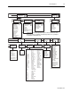

General Operation 4-5
1403-IN001A-US-P
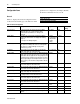
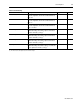
K-factor V / I
①
Crest V / I
①
TIF V / I
①
IEEE-519 V / I
①
IEEE %THD V / I
IEC %THD V / I
Harmonic 1/2 V / I
①
Harmonic 39/40 V / I
①
Harmonic 41 V / I
①
Harmonics
I4/Neutral
Same as
Program Configuration
except Read Only
Setpoint
01. .20
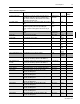
Display
Logs
Display
Configuration
Program
Setpoints
RIO Rack Address
RIO Group Number
RIO Last Rack
RIO
Baud Rate
Serial Delay
Serial Mode
RS-232/RS-485 Baud Rate
RS-485 Address
Logs
Min/Max Log
Logs
Event
Display
Setpoints
Display
Status
Event 01
Event 100
Type
Evaluation
High Limit
Low Limit
Pickup Delay
Dropout Delay
Action Type
Program
Configuration
Configuration
Communication
Configuration
Demand
Period Length
No. of Periods
Pulse Output
Pulse Parameter
Pulse Increment
Pulse Width
Setpoint
01. .20
Type
Evaluation
High Limit
Low Limit
Pickup Delay
Dropout Delay
Action Type
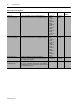
?
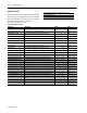
1 I
?
2 I
?
3 I
I4
Ave I
Pos Seq I
Neg Seq I
% Unbal I
?
1±
?
2 V
?
2±
?
3 V
?
3±
?
1 V
Aux V
Ave L±L V
Pos Seq V
Neg Seq V
% Unbal V
?
1±N V
?
2±N V
?
3±N V
Ave l±N V
Ave Freq.
Freq.
?
1 W
?
2 W
?
3 W
3
?
W
?
1 Var
?
2 Var
?
3 Var
3
?
Var
?
1 VA
?
2 VA
?
3 VA
3
?
VA
PF
?
1
PF
?
2
PF
?
3
PF Tot
Disp. PF
?
1
Disp. PF
?
2
Disp. PF
?
3
Disp. PF
TotDist. PF
?
1
Dist. PF
?
2
Dist. PF
?
3
Dist. PF Tot
Dmnd W
Dmnd VA
Dmnd Var
Dmnd I
V1 IEEE
%THD
V1 IEC %THD
V1 TIF
①
V1 Crest
①
V1 K-factor
①
I1 IEEE %THD
I1 IEC %THD
I1 TIF
①
I1 Crest
①
I1 K-factor
①
V2 IEEE
%THD
V2 IEC %THD
V2 TIF
①
V2 Crest
①
V2 K-factor
①
I2 IEEE %THD
I2 IEC %THD
I2 TIF
①
I2 Crest
①
I2 K-factor
①
V3 IEEE
%THD
V3 IEC %THD
V3 TIF
①
V3 Crest
①
V3 K-factor
①
I3 IEEE %THD
I3 IEC %THD
I3 TIF
①
I3 Crest
①
I3 K-factor
①
I4 IEEE %THD
I4 IEC %THD
I4 TIF
①
I4 Crest
①
I4 K-factor
①
Configuration
General
New Password
Voltage Mode
Filter Mode
①
Enable THD
②
PT & CT Ratio
Vaux & I4 Ratio
Vaux Volt Mode
Snapshot Period
Snapshot Buffer
Log Status Inp
Date Format
Time/Date
Max Isc
①
Max Dmnd Load 1
①
Phase Label
Aux Volt Label
Bulletin No.
Firmware Revision No.
Options Field
Device ID
Overall Status
ROM Status
RAM Status
EEPROM Status
NVRAM Status
Power Supply
Data Acquisition
Watchdog Timer
Clock Status
Battery Usage
Comm Card
No. of DMs/DM Status
Date/Time
Relay States
S1 Status/Counter
S2 Status/Counter
S3 Status/Counter
S4 Status/Counter
Output Word
Level 3
P
P P P P
P
P
P P P
Note: Configuration Communication parameters depend on which communication card is
being used. The above configuration Communication parameters are specifically for
the 1403-NSC Communication Card.