
Instruction Sheet User guide

4-10 General Operation
1403-IN001A-US-P
Commands
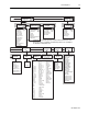
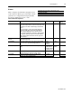
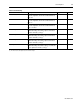
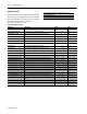
Table 4.3 displays the commands for the
Powermonitor II. The gray scale indicates which
commands are available through the Display Module,
the Smart Communication Card, or both.
Display Module and Smart Communication Card
Display Module Only
Smart Communication Card Only
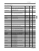
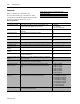
Table 4.3 Commands
Parameter Description Range
Force Relay #1 and #2 Forces Relay #1 and #2 to a known state in which the relay
remains at that state until the force is removed.
1 = Energize
2 = De-energize
4 = No Force (Automatic)
Clear Min/Max Log Resets the Min/Max log with the current real time metering
information.
No
Ye s
Clear Snapshot Log Clears all entries in the Snapshot log buffer. No
Ye s
Clear kWH Counter Resets the kWH counter to zero. No
Ye s
Clear kVarH Counter Resets the kVarH counter to zero. No
Ye s
Set kWH Counter Sets the kWH counter to the user specified value. (0 to clear)
-999.9x10
9
to 999.9x10
9
Set kVarH Counter Sets the kVarH counter to the user specified value. (0 to clear)
-999.9x10
9
to 999.9x10
9
Clear Status Input #1 to #4
Counter
Resets Status Input #1 to #4 Counter to zero. No
Ye s
Clear Battery Usage
Counter
Resets the Battery Usage Counter to zero. No
Ye s
Restore Factory Defaults Restores all of the Powermonitor II configuration parameters with
the factory default values.
No
Ye s
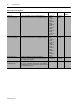
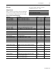
Clear Hold of Oscillograph
Data
(1)
Allows the user to enable oscillography when the oscillography
type is set to Hold.
No
Ye s
Trigger an Oscillograph
1
Allows the user to manually trigger a simultaneous 7 Channel 2-
Cycle and 2 Channel 12-Cycle oscillograph.
No
Ye s
Set Harmonic Analysis
Channel Request
1
Specifies the particular input channel for harmonic analysis
information to be returned through the Smart Communication
Card.
1 = Phase 1 Voltage
2 = Phase 1 Current
3 = Phase 2 Voltage
4 = Phase 2 Current
5 = Phase 3 Voltage
6 = Phase 3 Current
7 = Phase 4 Current
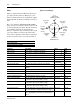
Set Oscillography Channel
Request
1
Specifies the particular input channel for an oscillogram to be
returned through the Smart Communication Card.
1 = 2 Cycle Phase 1 Voltage
2 = 2 Cycle Phase 1 Current
3 = 2 Cycle Phase 2 Voltage
4 = 2 Cycle Phase 2 Current
5 = 2 Cycle Phase 3 Voltage
6 = 2 Cycle Phase 3 Current
7 = 2 Cycle Phase 4 Current
8 = 12 Cycle Channel A
9 = 12 Cycle Channel B
Select Setpoint Number Specifies the particular setpoint information to be returned through
the Smart Communication Card.
1 to 20
(1) Available on 1403-MM only.