
Instruction Sheet User guide
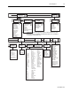

General Operation 4-13
1403-IN001A-US-P
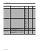
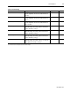
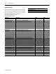
Phase 2 Distortion Power Factor The ratio between the magnitude of the fundamental and the
sum of the magnitudes for all of the current harmonics for
phase 2.
(2)
0 to 100 Percent
Phase 3 Distortion Power Factor The ratio between the magnitude of the fundamental and the
sum of the magnitudes for all of the current harmonics for
phase 3.
1
0 to 100 Percent
Total Distortion Power Factor The ratio between the magnitude of the fundamental and the
sum of the magnitudes for all of the current harmonics for
phase 1, 2, and 3.
1
0 to 100 Percent
Phase 1 Displacement Power Factor The cosine of the difference between the phase angle of the
fundamental voltage and current for phase 1; this value is
signed to show lead (+) or lag (-).
1
-100 to 100 Percent
Phase 2 Displacement Power Factor The cosine of the difference between the phase angle of the
fundamental voltage and current for phase 2; this value is
signed to show lead (+) or lag (-).
1
-100 to 100 Percent
Phase 3 Displacement Power Factor The cosine of the difference between the phase angle of the
fundamental voltage and current for phase 3; this value is
signed to show lead (+) or lag (-).
1
-100 to 100 Percent
Total Displacement Power Factor The cosine of the difference between the phase angle of the
fundamental voltage and current for phase 1, 2, and 3; this
value is signed to show lead (+) or lag (-).
1
-100 to 100 Percent
(1) This value has the same update rate as the harmonic analysis.
(2) This value has the same update rate as the harmonic analysis.
Table 4.5 Power Metering
Parameter Description Range Units