
Instruction Sheet User guide

4-24 General Operation
1403-IN001A-US-P
Whenever a setpoint event occurs, the setpoint setup
information is also logged. This information is
viewed via the Display Module by pressing the Enter
key (
↵
) when the setpoint event is displayed. This
information can also be retrieved via the Smart
Communication Card.
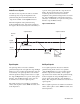
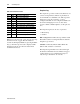
Snapshot Log
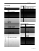
The snapshot log consists of 50 records. Each record
consists of 46 parameters. The list of parameters is
shown in Table 4.13 and Table 4.14. This log can be
updated via a setpoint occurrence or a user-
configured schedule. A user-configured schedule can
be an interval ranging from one second to three
years. To disable scheduled updates, set the period to
zero.
The Snapshot log has two modes of operation:
•
Fill and Stop
•
Circular
Fill and Stop fills the buffer and stops when it is full.
The buffer resumes recording information when the
Snapshot log is cleared.
Circular continuously fills the buffer. When the
buffer is full, old data is overwritten.
The Snapshot log information is retrieved through
the Smart Communication Card. All data is logged
together. However, for communication purposes
only, the log is divided into two blocks.
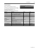
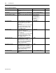
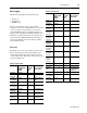
Table 4.12 Self-test Error Codes
Bits Hex Description
bit 0 0001h Master Module ROM Status
bit 1 0002h Master Module RAM Status
bit 2 0004h Master Module EEPROM Status
bit 3 0008h Master Module Non-volatile RAM Status
bit 4 0010h Master Module Power Supply Status
bit 5 0020h Master Module Data acquisition Status
bit 6 0040h Master Module Real Time Clock Status
bit 7 0080h Smart Communication Card Status
bit 8 0100h Display Module Status
bit 9 0200h Master Module Watchdog Timer Status
bits 10-
15
Reserved for factory use