
Instruction Sheet User guide


General Operation 4-31
1403-IN001A-US-P
Display Module # 1, #2, #3 Firmware Revision
Number
This parameter returns the firmware revision number
of the respective Display Module connected to the
fiber loop. It is available only through the Smart
Communication Card. This value is returned as an
integer such that 1.00 is represented as 100.
Master Module Auxiliary Frequency
This parameter returns the frequency of the AC
signal applied to the Auxiliary Voltage input to the
Powermonitor II when the configuration parameter
“Vaux Voltage Mode” is set to AC (or 0). This value
can only be viewed through the Smart
Communication Card.
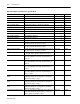
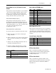
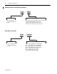
Master Module Fiber Loop Back Status
To perform a fiber loop back test follow these steps:
1. Remove any fiber optic cable connecting the
Display Modules.
2. Install a single fiber optic cable from the transmit
(Tx) port to the receive (Rx) port on the Master
Module.
3. Initiate a read of the Diagnostic/Status table via
the Smart Communication Card.
4. Examine the Master Module Fiber Loop Back
Status word within the Diagnostic/Status table.
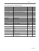
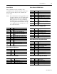
Master Module EEPROM Status
Master Module Device ID
This parameter returns the factory pre-programmed
value which is used as the default serial address if the
optional Cat. No. 1403-NSC Smart Communication
Card is installed. The value is within the range 0-250
inclusive.
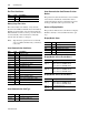
General Purpose Status Bits
BT Error Status Word 1
This word returns the Size/ID of the last block
written to the Powermonitor II through the Smart
Communication Card if any invalid data was
included in that block.
BT Error Status Word 2
This word returns the parameter number of the
invalid data item included in the last block written.
The last block written is identified by BT Error
Status Word 1.
Value
Returned
Description
0 A single fiber optic cable is incorrectly connected.
There may be a problem with the Master Module
fiber optic transceivers.
1 The fiber optic loop back test has passed.
Bits Hex Description
bit 0 0001h Summary status
bit 1 0002h Invalid configuration data status
bit 2 0004h Calibration block checksum status
bit 3 0008h Factory configuration block checksum
status
bit 4 0010h Configuration block 1 checksum status
bit 5 0020h Configuration block 2 checksum status
bit 6 0040h Read write status
bit 7 0080h Transfer status
bit 8 0100h Block write in progress status
bits 9-15 Reserved for factory use
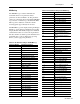
Bits Hex Description
bit 0
(1)
(1) Available on 1403-MM only.
0001h Oscillogram triggered and complete
bit 1 0002h Snapshot buffer full
bit 2
1
0004h Oscillogram triggered by a setpoint action
bits 3-15 Reserved for factory use