
User Manual, Firmware rev. 3.0 or LATER Owner's manual

Publication 1404-UM001F-EN-P - November 2009 153
Data Logging Chapter 7
Only mode 0, 1, and 2 are supported by DF1 and remote I/O
communication. In modes 0, 1, and 2 the client need only read the
results table repeatedly until the entire Trend Log is read. In modes
3…6 the client must alternate writes to select the next read-back
record with reads of the results table.
You may obtain the number of records in the Trend Log by reading
the Trend Log Configuration/Read-back Record Select
table, elements
7 and 8.
The number of records is (element 7) * 1000 + (element 8).
Only the following elements are needed during a record-selection
write:
• Password: -1
• DeviceNet unique write identifier: as applicable
• Reserved words: must be 0
• Read-back mode: see above
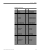
The Trend Log Results
table is a read-only table of 14 (DeviceNet
network) or 22 (all other communication options) floating-point
elements as follows:
• Reserved element: returns 0
• Internal identifier: increments by 1 to 15 for each trend log
record then rolls over to 0
• Time stamp: in 4-element timestamp format. See page 55
.
• User-selected parameters: parameters you selected when you
configured the Trend Log.
Min/Max Log
The Min/max Log maintains a time-stamped record of the minimum
and maximum values of up to 74 metering parameters. You can
monitor values over a day, a week, a month or any period to record
the highest and lowest values of voltage, current, or power factor.
Most industrial utility bills include a charge based on the maximum
demand recorded during the billing period. You could use the
Min/max log to provide that piece of data for generating an internal or
shadow billing report.