
User Manual, Firmware rev. 3.0 or LATER Owner's manual

Publication 1404-UM001F-EN-P - November 2009 175
Advanced Features Chapter 8
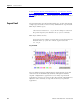
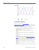
Setpoint #19 is setup to detect voltage sag and has the following
configuration data:
• Type = Voltage Sag
• Evaluation condition = Under forward
• High Limit = 90% Nominal System Voltage
• Low Limit = 90% Nominal System Voltage
• Action delay = 0
• Release delay = 0
• Output action = Capture oscillograph
Setpoint #20 is setup to detect voltage swell and has the following
configuration data:
• Type = Voltage Swell
• Evaluation condition = Over forward
• High Limit = 110% Nominal System Voltage
• Low Limit = 110% Nominal System Voltage
• Action delay = 0
• Release delay = 0
• Output action = Capture oscillograph
If the nominal system voltage setting is changed, the high and low
limits for setpoint #19 and #20 are automatically adjusted to 90% and
110% of the nominal system voltage.
Using Sag and Swell Detection
Follow these steps to effectively use sag and/or swell detection.
1. Set RMS result averaging to 0 (no averaging) for the quickest
setpoint response to changes in input voltage.
2. Alter setpoint configuration if necessary to adjust the sensitivity
to sags and/or swells.
If using the setpoint to trigger an oscillograph capture, make
sure there is at least one capture location that is clear and ready
to accept a new capture.
TIP
The setpoint limits reference the nominal line-to-line voltage for Delta
modes and the nominal line-to-neutral voltage for Wye and
single-phase modes.