
User Manual, Firmware rev. 3.0 or LATER Owner's manual


Publication 1404-UM001F-EN-P - November 2009 189
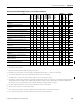
Powermonitor 3000 Data Tables Appendix A
Oscillograph Results Parameters R • N40 61 48 -
29 or 59
(14)
•• 244
Load Factor Log Configuration/Read-back Select
Parameters
R/W N41 16 49,50 - 6 •• 247
Load Factor Log Results Parameters R • F42 43 51 - 14 •• 248
Transient Analysis Configuration/Read-back Select
Parameters
R/W F43 44 52,53 - 13 • 249
Transient Analysis Metering Results Parameters R • F44 32 54 - 14 • 250
Transient Capture Clear/Read-back Data Select
Parameters
R/W N45 17 55,56 - 13 • 251
Transient Capture Results Parameters R • N46 60 57 -
29 or 59
(14)
• 252
Advanced Metering Configuration Parameters R/W N47 19 58,59 - 10 • 255
Harmonic Results; Odd Harmonics 43…63
Parameters
R • F48 45 60 - 14 • 256
Harmonic Results; Even Harmonics 42…62
Parameters
R • F49 46 61 - 14 • 257
Catalog Number and WIN Parameters R N51 50 64 32301 29 ••• 258
Network Demand Sync and Time Configuration
Parameters
(2)
R/W N52 - 65, 66 41901 20 ••• 260
Controller Command Parameters
(2)
W N53 - 67 42001 1 ••• 261
Daylight Saving Time Configuration Parameters R/W N54 47 68,69 42101 10 ••• 261
Time of Use Register Configuration Parameters R/W N55 49 70,71 42201 10 ••• 262
Time of Use Records – Real Energy and Demand
Parameters
R F56 51 72 32401 12 ••• 263
Time of Use Records – Reactive Energy and
Demand Parameters
R F57 52 73 32501 12 ••• 264
Time of Use Records – Apparent Energy and
Demand Parameters
R F58 53 74 32601 12 ••• 265
Single Password Write Parameters R/W N60 - 75,76 42701 1 ••• 266
Single Parameter Read Parameters R - - 80…
103
-1••• 267
(1)
Event log user comment feature has been removed from master firmware revision 3.1 and later.
(2)
Supported only on 1404-xxxxx-ENT-xx.
(3)
Data is most commonly read from this table by using the Indexed read method.
(4)
Powermonitor 3000 unit starts with file 9 to avoid any data-type incompatibility with SLC file numbers 1…8, which are of a fixed data type.
(5)
This is a reply to a PCCC diagnostic status request, used by RSWho to display text and an icon for the product.
(6)
Listed Modbus address is one-based. For zero-based addressing, subtract a value of one (1) from the listed address.
(7)
The default size is 2 input words and 2 output words for remote I/O. The input table (instance 1) default size is 6 words and is user configurable for DeviceNet, EtherNet/IP,
and ControlNet networks. Remote I/O tables and the default DeviceNet input channel are PLC/SLC controllers compatible, but if you reconfigure the DeviceNet input
channel (Instance 1), it may or may not be PLC/SLC controllers compatible (depending on the number of parameters configured).
(8)
Basic device configuration data table size is 8 elements for the M4 and M5, and 9 elements for the M6 and M8.
(9)
Table size increased in revision 3.1x of the master module firmware.
(10)
The size of the Trend log results table is 28 elements for the DeviceNet network and 44 elements for all other communication protocols.
(11)
The size of the Event log results table is 14 elements for M4/M5, 17 elements for M6 and 18 elements for the M8.
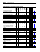
Summary of Powermonitor 3000 Data Tables for all Communication Options
Data Table Name and Description
(1)
Data
Access
Indexed
Reads
(3)
File No.
(4)
(DF1, CSP)
Remote I/O
BT Size
Assy
Instance
(CIP, DNet)
Modbus
Starting
Address
(6)
No. of
Elements
Applies to
Configur-
able
Refer to
Page
M4, M5
M6
M8