
User Manual, Firmware rev. 3.0 or LATER Owner's manual


Publication 1404-UM001F-EN-P - November 2009 191
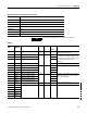
Powermonitor 3000 Data Tables Appendix A
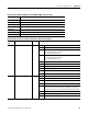
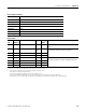
Remote I/O, DeviceNet, EtherNet/IP and ControlNet I/O Messaging Parameters
CSP File No. N/A
Remote I/O BT N/A
CIP Assy. Inst. 1 (Read), 2 (Write)
No. of Elements 2 (Default)
User Configurable Yes (DeviceNet, EtherNet/IP and ControlNet)
Data Type Integer (Selectable as Floating Point with DeviceNet, EtherNet/IP and ControlNet)
Data Access Read/Write
PM3000 Type All
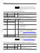
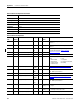
Remote I/O Discrete Data Provided by Powermonitor (Remote I/O Input Data)
Element
No.
Element name Range Comment
1 Relay, KYZ, and alarm bits - Bit Description
00…07 Reserved, used internally for BT information
08 Form C relay state (setpoint output flag 1)
0 = De-energized and not forced
1 = Energized and not forced
09 KYZ output state (setpoint output flag 2)
0 = De-energized and not forced
1 = Energized and not forced
10 Setpoint output flag 3 state
11 Setpoint output flag 4 state
12 Setpoint output flag 5 state
13 Setpoint output flag 6 state
14 Setpoint output flag 7 state
15 Setpoint output flag 8 state
2 Status input bits Bit Description
00 Status input 1 state
01 Status input 2 state
02…05 Reserved, returns 0
06 New oscillograph (M6, M8 only)
Indicates at least one capture has been triggered, saved, and is
ready to be read. This bit is cleared when all captures are cleared.
07…11 Reserved, returns 0
12…14 Reserved, used internally for BT information
15 Reserved, returns 0