
User Manual, Firmware rev. 3.0 or LATER Owner's manual

194 Publication 1404-UM001F-EN-P - November 2009
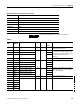
Appendix A Powermonitor 3000 Data Tables
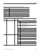
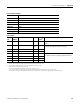
Basic Device Configuration Parameters
CSP File No. F10
Remote I/O BT 20
CIP Assy. Inst. 4 (Write), 5 (Read)
No. of Elements 8 (M4, M5), 9 (M6, M8)
User Configurable No
Data Type Floating point
Data Access Read / Write
PM3000 Type See table
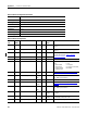
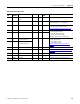
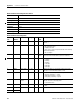
Basic Device Configuration
Element
No.
Modbus
Address
Element name M4
M5
M
6
M
8
Range Units Defaul
t
Value
Comment
0 40001-2 Password •••0…9999 - 0 Valid password required to change
configuration. Returns -1
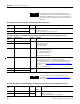
1 40003-4 Wiring mode •••0…8 - 6 0 = Delta 3 CT
1 = Delta 2 CT
2 = Direct Delta 3 CT
3 = Direct Delta 2 CT
4 = Open Delta 3 CT
5 = Open Delta 2 CT
6 = Wye
7 = Single Phase
8 = Demo
2 40005-6 Potential transformer (PT)
primary
•••1.0…
10,000,000.0
Volts 480.0 The high side of the PT ratio (xxx:xxx)
3 40007-8 PT secondary •••1.0…600.0 Volts 480.0 The low side of the PT ratio (xxx:xxx)
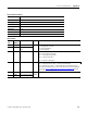
4 40009-10 I1/I2/I3 current
transformer (CT) Primary
•••1.0…
10,000,000.0
Amps 5.0 The high side of the CT ratio
(xxx:xxx)
5 40011-12 I1/I2/I3 CT secondary •••1.0…5.0 Amps 5.0 The low side of the CT ratio (xxx:xxx)
6 40013-14 I4 CT primary •••1.0…
10,000,000.0
Amps 5.0 The high side of the I4 CT ratio
(xxx:xxx)
7 40015-16 I4 CT secondary •••1.0…5.0 Amps 5.0 The low side of the I4 CT ratio
(xxx:xxx)
8 40017-18 Nominal system voltage • • 1.0…
10,000,000.0
Volts 480.0 Value is used in the default Sag and
Swell setpoints. (M6 and M8 only)
Nominal line-to-line voltage for Delta
mode and line-to-neutral for Wye and
single-phase modes