
User Manual, Firmware rev. 3.0 or LATER Owner's manual

250 Publication 1404-UM001F-EN-P - November 2009
Appendix A Powermonitor 3000 Data Tables
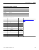
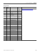
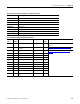
Transient Analysis Metering Results Parameters
CSP File No. F44
Remote I/O BT 32
CIP Assy. Inst. 54
No. of Elements 14
User Configurable No
Data Type Floating Point
Data Access Read only
PM3000 Type M8 only
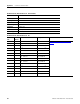
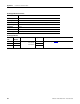
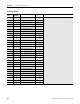
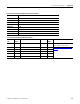
Transient Analysis Metering Results
Element
No.
Modbus
Address
Element Name Range Comment
0 - Capture number 1…6 Refer to
Reading Transient Analysis Metering Data on
page 181.
1 - Cycle number 1…12
2 - L1-L2 or L1-N Voltage
0.0…999.9x10
21
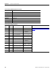
3 - L2-L3 or L2-N Voltage
0.0…999.9x10
21
4 - L3-L1 or L3-N Voltage
0.0…999.9x10
21
5 - L1 Current
0.0…999.9x10
21
6 - L2 Current
0.0…999.9x10
21
7 - L3 Current
0.0…999.9x10
21
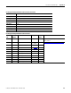
8 - L4 Current
0.0…999.9x10
21
9 - Voltage Index at trigger
-999.0x10
3
…999.0x10
3
10 - Current Index at trigger
-999.0x10
3
…999.0x10
3
11 - Voltage Trigger Threshold
0.0…999.0x10
3
12 - Current Trigger Threshold
0.0…999.0x10
3
13 - Unique Transient Capture ID 0…30,000