
User Manual, Firmware rev. 3.0 or LATER Owner's manual

Publication 1404-UM001F-EN-P - November 2009 301
Sample Applications Appendix C
MicroLogix Controller and Modbus Communication Network
This example reads and writes the power monitor date and time table
by using the MicroLogix 1400 controller using serial RS485
communications and the Modbus RTU protocol.
Refer to the Powermonitor 3000 Installation Instructions, publication
1404-IN007
for serial communications wiring.
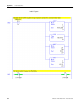
Serial Port Setup:
Either MicroLogix 1400 controller serial port may be configured as
Modbus master. This example uses Channel 2, which is a 9 pin
D-Shell RS-232 connector.
Powermonitor 3000 native port configuration: Modbus RTU, 9600
baud, node address 1, CRC
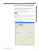
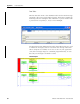
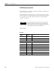
MicroLogix 1400 Port Configuration