
User Manual, Firmware rev. 3.0 or LATER Owner's manual

308 Publication 1404-UM001F-EN-P - November 2009
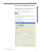
Appendix C Sample Applications
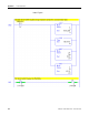
SLC 500 Sequencer Operation
This example uses a sequencer instruction and indirect addressing to
optimize program operation.
During initialization of Run mode, the sequencer input file is loaded
with the numbers corresponding to the two explicit message transfers
to be performed. Once Run mode has begun, the ladder program
remains in this mode.
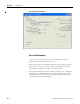
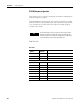
Data Files Used
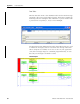
TIP
The speed at which the processor performs the messages may be
altered by resetting the On-Delay timer that is located within the
sequencer output rung. However, the availability of new data values
is controlled by the power monitor table update rate.
Data Files
Data File
Address
Number of
Elements
Description
N9 1 N9:0 Sequencer Output
N10 Variable N10:0 Sequencer Input
R6:0 Sequencer Control
Message Read Data Table Locations
(Control/Data)
N20 / F30 14 Voltage/Current Data
N21 / F31 13 Real-Time Power
N22 / F32 13 Power Factor
N23 / N33 23 kWh and kVAh
N24 / N34 23 kVarh
N25 / F35 10 Demand
N26 / N36 27 Diagnostic