User Manual Combination Generator Control Module Catalog Number 1407-CGCM
Important User Information Solid-state equipment has operational characteristics differing from those of electromechanical equipment. Safety Guidelines for the Application, Installation and Maintenance of Solid State Controls (publication SGI-1.1 available from your local Rockwell Automation® sales office or online at http://www.rockwellautomation.com/literature/) describes some important differences between solid-state equipment and hard-wired electromechanical devices.
Summary of Changes This manual contains new and updated information. Changes throughout this revision are marked by change bars, as shown to the right of this paragraph. New and Updated Information This table contains the changes made to this revision.
Summary of Changes Notes: 4 Rockwell Automation Publication 1407-UM001G-EN-P - April 2013
Table of Contents Preface Additional Resources . . . . . . . . . . . . . . . . . . . . . . . . . . . . . . . . . . . . . . . . . . . . . . 7 Chapter 1 General Information Introduction . . . . . . . . . . . . . . . . . . . . . . . . . . . . . . . . . . . . . . . . . . . . . . . . . . . . . 9 Functions . . . . . . . . . . . . . . . . . . . . . . . . . . . . . . . . . . . . . . . . . . . . . . . . . . . . . . . . 9 Chapter 2 Installation Mounting Requirements . . . . . . . . . . . . . . . . . . . . . . .
Table of Contents Appendix B CGCM Unit Math Models Introduction . . . . . . . . . . . . . . . . . . . . . . . . . . . . . . . . . . . . . . . . . . . . . . . . . . . . Synchronous Machine Terminal Voltage Transducer and Load Compensator Model. . . . . . . . . . . . . . . . . . . . . . . . . . . . . . . . . . . . . . . . . . . . . Voltage Regulator . . . . . . . . . . . . . . . . . . . . . . . . . . . . . . . . . . . . . . . . . . . . . . . VAR/Power Factor Controller . . . . . . . . . . . . . . . . . . .
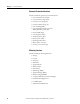
Preface The information in this manual applies to the 1407-CGCM module, Series C, Revision D, with host firmware revision 4.9 and ControlNet firmware revision 1.11. The manual notes differences with earlier versions of the product where they occur. Additional Resources These documents contain additional information concerning related products from Rockwell Automation. Resource Description Safety Guidelines for the Application, Installation and Maintenance of Solid State Controls, publication SGI-1.
Preface Notes: 8 Rockwell Automation Publication 1407-UM001G-EN-P - April 2013
Chapter 1 General Information Introduction The Combination Generator Control Module (CGCM unit) is a microprocessor-based control and protection device. The CGCM unit is designed to integrate with a Logix family programmable controller to provide generator control, protection and synchronization functions. Programmability of system parameters, regulation settings, and protective functions enable the CGCM unit to be used in a wide range of applications.
Chapter 1 General Information Generator Protection Functions This list contains the generator protection functions: • Loss of excitation current (40) • Over-excitation voltage (59F) • Generator over-voltage (59) • Generator under-voltage (27) • Loss of sensing (60FL) • Loss of permanent magnet generator (PMG/Excitation power) (27) • Reverse VAR (40Q) • Over-frequency (81O) • Under-frequency (81U) • Reverse power (32R) • Rotating diode monitor • Phase rotation error (47) • Generator over-current (51) Mete
General Information Chapter 1 Inputs This list contains the inputs for the CGCM unit: • Single-phase or 3-phase true rms generator voltage sensing • Single-phase dual bus or 3-phase single bus voltage sensing • 3-phase generator current sensing (1 or 5 A nominal) • Single-phase cross current loop 1 or 5 A current transformer (CT) input • Auxiliary ±10V DC input providing remote control of the setpoints • DC power input Outputs This list contains the outputs for the CGCM unit: • Pulse-width modulated outp
Chapter 1 General Information Notes: 12 Rockwell Automation Publication 1407-UM001G-EN-P - April 2013
Chapter 2 Installation Mounting Requirements This equipment is intended for use in a Pollution Degree 2 Industrial Environment, in over-voltage Category II applications (as defined by IEC publication 60664-1). Because the units contain a heat sink, they must be mounted vertically. Any other mounting angle reduces the heat dissipation capabilities of the units, possibly leading to premature failure of critical components.
Installation Chapter 2 Figure 1 - CGCM Unit Overall Dimensions 247.7 (9.75) 228.6 (9.00) 9.7 (0.38) ID (+) 1A V Gen A ID (+) 5A V Gen B V Gen C V Gen N ID (-) CNA CNB TB5 I3 (+) 1A I3 (+) 5A I3 (-) 152.4 (6.00) I2 (+) 1A I2 (+) 5A I2 (-) V Bus A I1 (+) 1A V Bus B V Bus C V Bus N I1 (+) 5A PMG A PMG B TB6 I1 (-) PMG C SHLD 1 SHLD 1 TB3 SHLD 2 SHLD 2 TB1 EXC (+) EXC (-) 152.4 (6.
Installation Electrical Connections Chapter 2 The CGCM unit’s connections are dependent on the application and excitation scheme. All inputs or outputs cannot be used in a given installation. Incorrect wiring can result in damage to the unit. Connect the CGCM unit’s terminals with copper wire rated for a minimum of 600V. General appliance wire rated for minimum temperatures of 105 °C (221 °F) is acceptable. All wire must be copper. Select circuit conductors based on good design practice.
Chapter 2 Installation Table 1 - Terminal Block Label Description Terminal Block Wire Gauge Range Label Description TB3 2.6…2.
Installation Chapter 2 Excitation Power Excitation power is wired to the PMG terminals, whether connected to the generator output (Shunt Excited) or to a PMG. Connect shunt excited inputs with a voltage transformer (VT). PMG inputs are on TB1 and are labeled PMG A, PMG B, and PMG C, illustrating their respective phase relationships. Single-phase excitation power must be connected to terminals PMG A and PMG C. Twisted, shielded cabling is required for the PMG inputs. Refer to the wiring diagrams below.
Chapter 2 Installation Figure 5 - Excitation Power Connections, 3-phase Shunt Fuse PMG A PMG B PMG C SHLD 1 SHLD 1 Fuse TB1 B A C G Figure 6 - Excitation Power Connections, AREP Generator TIP 18 This diagram is based on a Leroy Somer 300 kW AREP (auxiliary winding regulation excitation principle) machine. Details can differ on other machines.
Installation Chapter 2 Excitation Output The excitation outputs are on TB2 and are labeled EXC(+) and EXC(-). Twisted, shielded cabling is required for the excitation outputs. Figure 7 - Excitation Output Connections, Non-redundant CGCM Exciter voltage connections TB2 Shld2 Shld2 EXC (-) EXC (+) Exciter field When the redundancy function is used, three or four external flyback diodes in series must be placed across the generator field winding. Refer to the redundancy wiring diagrams on pages 31…32.
Chapter 2 Installation Chassis Ground The terminal labeled CH GND, on TB4, is the chassis ground. Ground studs are also provided on the lower part of the mounting flanges and are internally connected to the CH GND terminal. Connect chassis ground to earth ground with minimum 2.6 mm2 (10 AWG) copper wire attached to either stud on the lower part of either side of the unit and to the CH GND terminal with 1.6 mm2 (14 AWG) copper wire.
Installation Chapter 2 Generator Current Sensing CGCM units provide 3-phase AC current sensing with provisions for 1 A and 5 A nominal sensing ranges. The inputs for 3-phase current sensing are on TB3. The ID (+) and ID (-) terminals are used for systems connected in a cross-current compensation system.
Installation Chapter 2 Figure 9 - Voltage and Current Connection for Two (or three) Transformer Delta Bus and Two (or three) Transformer Delta Generator System L1 L2 L3 Fuse Optional Ground Fuse Fuse Use of a third potential transformer is optional. The CGCM unit can be connected in either open or closed delta. VBus A VBus B VBus C VBus N TB 6 CB Fuse Optional Ground VGen A VGen B VGen C VGen N Fuse Fuse Use of a third potential transformer is optional.
Installation Chapter 2 Figure 10 - Voltage and Current Connection for Four-wire Wye Bus and Four-wire Wye Generator System with Grounded Neutral L1 L2 L3 N Fuse Fuse VBus A VBus B VBus C Fuse VBus N TB 6 CB Fuse Fuse VGen A VGen B VGen C VGen N Fuse TB5 To optional cross-current reactive compensation loop.
Installation Chapter 2 Figure 11 - Voltage and Current Connection for Four-wire Wye Bus and Two (or three) Transformer Delta Generator System L1 L2 L3 N Fus e Fuse VB u s A VB u s B VB u s C Fu se VB u s N TB 6 CB Fuse Optional Ground Fuse Fu se VGe n A VGe n B VGe n C VGe n N Use of a third potential transformer is optional. The CGCM unit can be connected in either open or closed delta. TB5 To optional cross-current reactive compensation loop.
Installation Chapter 2 Figure 12 - Voltage and Current Connection for Two (or three) Transformer Delta Bus and Four-wire Wye Generator System L1 L2 L3 Fu se Optional Ground VB us A VBus B VB us C Fu se VB us N TB 6 Fuse Use of a third potential transformer is optional. The CGCM unit can be connected in either open or closed delta. CB Fuse Fuse V Gen A VGe n B V Gen C V Gen N Fuse TB 5 To optional cross-current reactive compensation loop.
Installation Chapter 2 Figure 13 - Voltage and Current Connection for Three-wire Wye Bus and Four-wire Wye Generator System with Grounded Neutral L 1 L2 L3 Fuse Fuse VBus A VBus B VBus C Fuse VBus N TB 6 CB Fuse Fuse VGen A VGen B VGen C VGen N Fuse TB5 To optional cross-current reactive compensation loop.
Installation Chapter 2 Figure 14 - Voltage and Current Connection for Dual Breaker Bus and Two (or three) Transformer Delta Generator System L1 A L 2A L 3 A L1 B L 2B L 3 B Fu s e VB us A VB us B VB us C Fu se VBus N TB 6 CB CB Fuse Optional Ground VGen VGen VGen VGen Fuse TB 5 Fus e Use of a third potential transformer is optional. The CGCM unit can be connected in either open or closed delta. A B C N To optional crosscurrent reactive compensation loop.
Installation Chapter 2 Figure 15 - Voltage and Current Connection for Dual Breaker Bus and Four-wire Wye Generator System L1 A L 2A L3 A L1B L2 B L3B Fuse VBus A VBus B VBus C Fuse VBus N TB 6 CB CB Fuse Fuse V Gen A V Gen B V Gen C V Gen N Fuse TB 5 To optional crosscurrent reactive compensation loop.
Installation Chapter 2 Figure 16 - Voltage and Current Connection for Single Phase Bus and Single-phase Generator System L1 L2 L3 Fuse VBus A VBus B VBus C VBus N TB 6 CB VGen VGen VGen VGen Fuse A B C N TB 5 To optional cross-current reactive compensation loop.
Chapter 2 Installation Figure 17 - Current Connections for 3-phase Delta Generator with Two CTs The connections shown in this diagram can be used if only two CTs are available in the generator circuit. Two CTs can be used only with a three-wire delta generator. The circuit shown in this diagram can be substituted for the CT connections shown in Figures 9, 11, 14, and 16.
Installation Chapter 2 Fault Relay Output The fault relay output is an open-collector sinking output. The fault relay output terminals are on TB4 and are labeled FLT. The following illustration shows a typical connection. Figure 18 - Typical Fault Relay Connection Redundancy Relay Output The redundancy relay output is an open-collector sinking output. The redundancy relay output terminals are on TB4 and are labeled RD RLY. The following figures illustrate typical redundancy connections.
Chapter 2 Installation Figure 20 - Typical Redundancy Current Sensing Connection Diagram Generator Current Connections TB 3 TB 3 Customer Supplied CT Shorting Blocks or Test Block I1 ( -) I1 (+) 5 A I1 (+) 1 A Typical connection for one current input. Other current inputs (including the cross-current input) should duplicate.
Installation Chapter 2 Real-power Load Sharing The load sharing terminals connect to a 0…5V DC, internally powered circuit. The load sharing terminals are on TB7 and are labeled LS(+) and LS(-). Terminal SHLD4 is provided to land the cable shield. Twisted, shielded cabling is required for the load sharing connections. Figure 23 - Real-power Load Sharing LS (+) LS (-) SHLD 4 TB 7 LS (+) LS (-) SHLD 4 CGCM 1 TB7 CGCM2 LS (+) LS (-) SHL D 4 TB 7 CGCM3 Ground shield at only one point.
Chapter 2 Installation Figure 24 - Cross-current (reactive differential) Compensation Connection Diagram L 1 L2 L3 Crosscurrent CT (typical) ID (+ ) 1A ID (+ ) 5A ID (-) A B G Customer Supplied CT Shorting Switch or Test Block (typical) C G1 L1 L2 TB 3 L3 ID (+ ) 1 A ID (+ ) 5 A ID ( -) TB 3 A B G C G2 L1 L2 L3 ID (+ ) 1 A ID (+ ) 5 A ID ( -) TB 3 A B G C Ground cross-current loop at only one point (optional).
Installation Chapter 2 Communication Connectors and Settings There are three ports on the unit: the factory calibration port, the redundancy port (COM1), and the ControlNet network port. Factory Calibration Port The factory calibration port is not intended for use by anyone other than qualified factory representatives. Redundancy Port (COM1) The DB-9 female connector on the bottom side of the CGCM unit is used for communication with another CGCM unit when operating in a redundant system configuration.
Chapter 2 Installation ControlNet Network Port Two ControlNet tap cables and channel labels are included with the 1407-CGCM unit. You can use the mounting fasteners provided on the right-hand side of the unit chassis to fasten the tap cables. Minimum bend radius for the ControlNet tap cables is 38 mm (1.5 in.). Take care not to kink or pinch the ControlNet tap cable or bend it more sharply than the minimum radius.
Chapter 3 CGCM Unit Operation This section provides a operational description of the CGCM unit’s functions. The CGCM unit incorporates hardware inputs and outputs, software inputs and outputs to a Logix family programmable controller, configuration settings, and its internal control algorithms to provide the regulation, synchronizing, and protection functions described in this section. For information on configuring the CGCM unit, see Chapter 4, Configuration.
Chapter 3 CGCM Unit Operation Inputs and Outputs The figure below shows the front panel layout of the CGCM unit. Input and output connections are made through the terminal blocks TB1…TB7.
CGCM Unit Operation Chapter 3 The CGCM unit uses voltages measured through the generator voltage sensing inputs for generator voltage, VAR and/or power factor regulation, kW and kVAR load sharing, synchronization, metering, and protection. The inputs accept signals with up to 40% Total Harmonic Distortion (THD) and are connected for single-phase and 3-phase applications. The generator voltage inputs are internally scaled by the CGCM unit according to its transformer configuration settings.
Chapter 3 CGCM Unit Operation Auxiliary Input This input is an analog voltage (-10…10V DC), and provides a means to remotely adjust the regulation point of the generator. Resistive isolation is provided through the use of differential amplifiers. The auxiliary input terminals are labeled VREF(+) and VREF(-). Power Inputs The unit has two types of power inputs: control power inputs and excitation power inputs.
CGCM Unit Operation Chapter 3 Analog Outputs The unit has two types of analog outputs: excitation output and real power load sharing. Excitation Output The CGCM unit Pulse Width Modulated (PWM) power stage provides DC generator exciter field current. The excitation power stage is designed to accommodate up to 125V DC (nominal) field voltages. Refer to Excitation Control Modes on page 44 for a description of operation.
Chapter 3 CGCM Unit Operation Discrete Outputs The CGCM unit provides two discrete open collector outputs, the fault output and the redundancy relay output. These are sinking type outputs internally connected to the control power BAT(-) supply. They are intended to drive a user-supplied relay connected between the control power BAT(+) supply and the applicable discrete output terminal. Fault Output The fault output can be used to annunciate a fault via a user-supplied relay.
CGCM Unit Operation Chapter 3 Software Inputs and Outputs Your Logix family host programmable controller must include the hardware and communication interfaces with the generator, prime mover, power system, and balance of plant that are not specifically included in the CGCM unit module. The software interface between the CGCM unit and its host controller is made via the ControlNet software interface. The specific interface consists of several assembly instances, or data tables.
Chapter 3 CGCM Unit Operation Excitation Control Modes The CGCM unit controls the DC excitation current of the generator exciter based on a number of factors, including the following: • The selected control mode • The configuration of the CGCM unit including gains • Measured generator voltage and current • The applicable setpoint or setpoints • The value of the Auxiliary Input • Various limiting functions The CGCM unit offers several modes of regulation that are selected and activated by using the softwar
CGCM Unit Operation Chapter 3 Field Current Regulation Mode (FCR) FCR mode provides manual control of the excitation current. In FCR mode, the CGCM unit measures and controls its field excitation current output to maintain the commanded field current setpoint. The FCR feedback loop includes adjustable proportional, integral, and derivative gains. In FCR mode, automatic voltage control, reactive power control, power factor control, over-excitation limiting, and under-excitation limiting are disabled.
Chapter 3 CGCM Unit Operation To activate droop: • the metering CTs and generator VTs must be properly connected and configured. • the desired droop setpoint must be written to the V_DroopSetpt tag. • excitation enabled (tag SoftwareExcEn = 1). • remote Excitation Enable On (discrete input). • the CGCM unit must be in AVR mode (tag AVR_FCR_Select = 0). • droop must be enabled (V_DroopEn tag = 1). • droop must be selected (Droop_CCC_Select tag = 0).
CGCM Unit Operation Chapter 3 Auxiliary Input Regulation Adjustment The auxiliary input provides a means to remotely adjust the regulation point of the generator. This analog voltage (-10…10V DC) input signal changes the setpoint of the selected operating mode by one percent of the applicable rated value for each volt applied (positive or negative), multiplied by the auxiliary gain setting for AVR/FCR or VAR/PF. Refer to Chapter 4 for more information. Auxiliary input gain settings range from -99…99.
Chapter 3 CGCM Unit Operation Reactive Power Regulation Mode (VAR) In VAR mode, the CGCM unit controls field excitation current output to maintain the commanded reactive power setpoint. The CGCM unit uses the measured generator voltages and currents to calculate reactive power. The VAR feedback loop includes adjustable proportional and integral gains. To activate VAR mode: • the metering CTs and VTs must be properly connected and configured. • the VAR mode gains must be set.
CGCM Unit Operation Chapter 3 If the generator is not up to speed when the soft start begins, the voltage increases but only to the level determined by Volts/Hz limiting. When the unit is operating in FCR mode, soft start operates as it does in the AVR mode, with the field current, rather than the generator voltage, being the controlled parameter. To activate soft start mode: • the Soft Start Initial Voltage (tag SoftStart_InitLevel) and Soft Start Time (tag SoftStartTime) parameters must be set.
Chapter 3 CGCM Unit Operation The tag SetptTraverseActive = 1 when the CGCM unit is traversing between the internal tracking setpoint and the new operating mode's setpoint. The tag = 0 when the operating point has completed traversing to the new mode's setpoint. This tag is used by the host Logix controller to determine when the new mode has taken control. Limiting Functions This section discusses the different types of limiting functions the CGCM unit provides.
CGCM Unit Operation Chapter 3 Volts/Hertz Limit Volts/Hertz limiting acts to reduce the generator output voltage by an amount proportional to generator frequency. This is done to protect the generator from overheating and reduce the impact on the prime mover when adding a large load. When the generator frequency drops, the voltage setpoint is automatically adjusted by the CGCM unit so that generator voltage follows the under-frequency slope.
Chapter 3 CGCM Unit Operation Over-excitation Limit Over-excitation limiting (OEL) operates in all modes except FCR. The CGCM unit senses and limits the field current to prevent field overheating. When the limit is reached, the limiter function overrides AVR, VAR, or Power Factor modes to limit field current to the preset level. OEL operates in the area above the Field Winding Heating Limitation curve in the generator capability curve.
CGCM Unit Operation Chapter 3 The CGCM unit also uses two counters, the reset counter and the time limit counter. The counters are used to prevent excessive heating of the exciter field that can be a result of repeated over-excitation. The time limit counter monitors the duration of an over-excitation condition. The reset counter counts backward from either the high OEL time setting or the sum of the high and medium OEL times, depending on the value of the time limit counter.
Chapter 3 CGCM Unit Operation Figure 34 - Typical UEL Limiting Curve Real Power Generate (W) x 1000 0.0 7.5k 15.0k 22.5k 30.0k 37.5k 45.0k Reactive Power Absorb (var) x 1000 0.0 2.5k 5.0k 7.5k 10.0k 12.5k 15.0k Protection Functions The CGCM unit detects the fault conditions listed and described below. Faults detected by the CGCM unit are communicated to the host Logix programmable controller. Fault flags are communicated in the Scheduled Read table.
CGCM Unit Operation Chapter 3 The CGCM unit can be used as primary protection in applications not requiring utility grade protection or in utility applications where the authority having jurisdiction has approved the CGCM unit for use as primary protection. In applications requiring utility grade protection, where the local authority has not evaluated or approved the CGCM unit, the CGCM unit can be used for secondary protection in conjunction with a primary protection system.
Chapter 3 CGCM Unit Operation Loss of Sensing (60FL) For three-wire and four-wire sensing, Loss of Sensing detection is based on the logical combination of several conditions. They include these conditions: 1. The average positive sequence voltage is greater than 8.8% of the AVR setpoint. 2. The negative sequence voltage is greater than 25% of the positive sequence voltage. 3. The negative sequence current is less than 17.7% of the positive sequence current. 4.
CGCM Unit Operation Chapter 3 Loss of Excitation Power (PMG) (27) If voltage to the PMG excitation power inputs falls below 10V AC for approximately 400 ms or more, a Loss of Excitation power fault occurs. When single phase PMG is selected, the CGCM unit senses phases A and C for this function. This function is disabled when Shunt excitation is selected, the EngineIdle tag is set, or the host Logix controller is in Program mode. If this fault occurs, tag LossPMGFlt = 1 in the Scheduled Read table.
Chapter 3 CGCM Unit Operation Over-frequency (81O) When generator frequency exceeds the over-frequency setpoint for a specified amount of time, a definite time over-frequency fault occurs. Once the frequency drops below the threshold, the over-frequency fault timer is reset. If this fault occurs, tag OvrFreqFlt = 1 in the Scheduled Read table.
CGCM Unit Operation Chapter 3 The Rotating Diode fault is inhibited if the field current is less than 1.5 A DC or if the generator frequency is outside the range of 45…70 Hz. Phase Rotation Fault (47) The CGCM unit calculates the negative sequence voltage of the 3-phase generator voltage sensing input. When the generator phase rotation is opposite to the wiring rotation you configured, the level of the generator negative sequence voltage increases to approximately 100%.
Chapter 3 CGCM Unit Operation Synchronizing Connection Schemes The CGCM unit provides information that its host Logix controller uses to synchronize the generator output voltage, frequency, and phase to a reference power system, or bus. 3-phase, dual bus, and single-phase connection schemes are described below. • 3-phase In this scheme, the 3-phase output of the generator and all three phases of the reference system are connected to the CGCM unit.
CGCM Unit Operation Chapter 3 To enable single-phase synchronizing, select the Generator VT Configuration as Single-phase. Configurable Synchronization Parameters The CGCM unit provides a number of configurable settings to facilitate synchronizing between systems with different voltages and metering configurations. Please refer to Chapter 4 for more information.
Chapter 3 CGCM Unit Operation • Check Synchronization The host controller sets the CheckSyncEn tag to enable Check Synchronization mode. This mode is the same as the Automatic Synchronization mode except the CGCM unit does not set a close breaker tag. This mode is useful for testing the system. • Initiate Synchronization The host Logix controller sets the InitiateSync tag to begin the synchronization process. This tag must remain set during the entire process.
CGCM Unit Operation Chapter 3 Synchronizing Control Software Interface When synchronization is active, the CGCM unit adjusts the values of the Scheduled Read table tags as described below.
Chapter 3 CGCM Unit Operation Limit defines the maximum per unit load share error reported to the host controller. Rate defines the maximum change in the load share error per CGCM unit update cycle, expressed in percent of rated kilowatts per second. For example, if a change of load of 50% is required and the rate set for 10% per second, the change takes 5 seconds to complete.
CGCM Unit Operation Chapter 3 Table 3 - Metered Parameter Accuracy Metered Parameter Metering Wiring Mode Single-phase Delta Three-wire Wye Four-wire Wye Dual-bus Gen Voltages, 3, L-L CA AB, BC, CA AB, BC, CA AB, BC, CA - Gen Voltage, avg, L-L Yes (=CA) Yes Yes Yes - Gen Voltages, 3, L-N N/A N/A N/A A, B, C - Gen Voltage, avg, L-N N/A N/A N/A Yes - Gen Currents, 3 A, B, C A, B, C A, B, C A, B, C - Gen Current, avg Yes Yes Yes Yes - Gen Kilowatts, 3 N/A N/A N/A
Chapter 3 CGCM Unit Operation Figure 36 - Power System Sign Conventions Forward Reactive Power Flow (export) II I watts negative (-) watts positive (+) vars positive (+) vars positive (+) power factor lagging (+) power factor lagging (+) Forward Real Power Flow (export) Reverse Real Power Flow (import) watts negative (-) vars negative (-) power factor leading (-) watts positive (+) vars negative (-) power factor leading (-) III IV Reverse Reactive Power Flow (import) Redundancy The CGCM unit is c
CGCM Unit Operation Chapter 3 If a loss of communication between redundant CGCM units occurs, the primary CGCM unit remains primary and the secondary CGCM unit switches to primary also. Because in this state both units are supplying current to the field, the host Logix programmable controller must be programmed to take corrective action (for example disable excitation to one CGCM unit) when this condition occurs.
Chapter 3 CGCM Unit Operation Once the primary and secondary CGCM unit roles have been established by the host controller, they remain in their respective modes indefinitely. You can force a transfer by disabling excitation on the primary unit. This causes the secondary unit to sense a loss of tracking information, switch to Primary mode, and take over-excitation control.
CGCM Unit Operation Chapter 3 The redundant tracking delay setting adjusts the delay of the tracking function to prevent the secondary CGCM unit output from being adjusted into an undesirable condition. For example, with AVR mode active in the primary CGCM unit, if the generator sensing VT fails open the excitation output goes to a full-on state. Applying a tracking delay reduces the likelihood of this undesirable operating point to be transferred to the secondary CGCM unit when it takes over control.
Chapter 3 CGCM Unit Operation Notes: 70 Rockwell Automation Publication 1407-UM001G-EN-P - April 2013
Chapter 4 CGCM Unit Configuration Introduction This section provides a generic set-up and verification procedure for power generation systems by using the CGCM unit and RSLogix 5000 software. The various configuration parameters required to customize the device to a specific application are presented. Because every application is unique, read this section carefully and make sure that the configuration entries are appropriate for the system being implemented.
Chapter 4 CGCM Unit Configuration • Generator capability curve • Generator decrement curve Consult with the generator manufacturer to be sure that you have the correct data. Record System Parameters Verify and record system information and generator information required for configuration of the CGCM unit. Typically this information can be obtained from the generator nameplate, manufacturer’s data sheets, and system electrical drawings.
CGCM Unit Configuration Chapter 4 2. Select 1407-CGCM and then enter the Major Revision of the host firmware (for example 4 where the host firmware revision is 4.x or 2 where the host firmware is revision 2.x). IMPORTANT You must enter the correct Major Revision at this time. Do not change the Major Revision number once the module is created. If you need to change it at a later time, you must delete the module and configure a new module. 3. Click OK. The Module Properties dialog box appears. 4.
Chapter 4 CGCM Unit Configuration Once you have added the module, you must schedule the connection to the CGCM unit with RSNetWorx for ControlNet software. Electronic Keying ATTENTION: Be extremely cautious when using the disable keying option; if used incorrectly, this option can lead to personal injury or death, property damage or economic loss. Although the CGCM unit does not physically reside in a ControlLogix chassis, electronic keying provides protection against module mismatch.
CGCM Unit Configuration Chapter 4 Applying the Configuration to the CGCM Unit The configuration tabs provide a simple way for you to enter and edit CGCM unit configuration parameters. Changes you make to the configuration are not always immediately sent to the unit. The configuration data is stored in two controller tags in the ControlLogix controller, the Configuration tag and the Unscheduled Write tag. Refer to Chapter 6 for details on these data tags.
Chapter 4 CGCM Unit Configuration RSLogix 5000 software performs configuration data checking as specified by the limits shown in the data tables. The data checking verifies that the entry is within range for the device, however, it does not verify that it is reasonable for the application. You must be sure that the entry is reasonable for the specific application. If you enter an out-of range parameter in a Configuration tab, a message box reports the error and the appropriate limits.
CGCM Unit Configuration Chapter 4 Rated Power - Sets the generator's rated power in Watts. Sets the value of tag GenRated_W in the Configuration table. Rated Field Voltage - Sets the generator exciter's rated field voltage while the generator is operating at rated voltage, kW, and kVAR. Sets the value of tag GenRatedExcV in the Configuration table. Rated Field Current - Sets the generator exciter's rated field current, in amperes DC.
Chapter 4 CGCM Unit Configuration • Generator VT Configuration - The generator VT configuration selections are (1) single-phase, (2) two-transformer open delta, (3) three-wire wye, and (4) four-wire wye. Use the two-transformer open delta setting for any delta configuration. This parameter is stored in the tag GenVT_Config in the configuration table. • Generator VT Primary Voltage - The primary voltage rating of the generator voltage transformer is stored in tag GenVT_Pri_V in the configuration table.
CGCM Unit Configuration Chapter 4 • Cross Current CT Secondary Current - The secondary current rating of the cross current generator current transformer connected to the CGCM unit terminals ID (+) and ID (-).This parameter is stored in tag CCCT_Sec_I in the configuration table. It is used for monitoring generator reactive current in paralleling applications. EXAMPLE As an example, consider a generator rated at 12,470V and 450 A. VTs with ratios of 100:1 and CTs with ratios of 500:5 are used.
Chapter 4 CGCM Unit Configuration • Soft Start Time - The desired time to ramp up from the Soft Start Initial Voltage to the nominal generator output voltage. This parameter is stored in tag SoftStartTime in the Configuration table and is expressed in seconds. • Over-excitation Voltage Setpoint - Establishes the over-excitation voltage setpoint used by the CGCM unit. This setpoint is stored in tag OvrExcV_Setpt in the configuration table and scaled in volts.
CGCM Unit Configuration Chapter 4 • Rotating Diode Fault Delay - Establishes the time duration that the ripple current must be at or above the fault level before the CGCM unit annunciates a rotating diode fault. Tag DiodeMonitorTimeDelay in the configuration table stores this value, expressed in seconds. TIP Refer to Chapter 5 for more information on configuring rotating diode protection parameters. • Excitation Select – Selects the excitation power source.
Chapter 4 CGCM Unit Configuration Volts/Hz Tab The Volts/Hz tab is used to configure the unit’s settings related to operation of the Volts/Hz compensation function. The parameters define a curve, which determines the Volts/Hz response. • Volts per Hertz Upper Knee Frequency - Establishes the frequency at which the V/Hz characteristic starts to reduce the generator voltage as a function of generator frequency. Tag VperHz_HiKneeFreq in the configuration table stores this value, expressed in Hertz.
CGCM Unit Configuration Chapter 4 • Volts per Hertz Lower Slope - Establishes the rate at which the V/Hz characteristic reduces the generator voltage as a function of generator frequency below the Lower Knee Frequency setting. Tag VperHz_LoSlope in the configuration table stores this value, expressed as a number that reflects per unit change in voltage for each per unit change in frequency. • The Validate and graph button becomes active when a parameter has been changed.
Chapter 4 CGCM Unit Configuration • Over-excitation Limiting Enable – Select this check box to enable over-excitation limiting. Tag OEL_En in the configuration table stores this parameter. In addition to selecting the check box, which sets the OEL_En tag in the configuration table, the OEL_En tag in the Output (Scheduled Write) Data table must also be set to enable this function. In Series B deices with firmware revision 3.
CGCM Unit Configuration Chapter 4 • Validate and Graph button – Updates the graph in the OEL tab after entering new values. Related Parameters • GenRatedExcI • OEL_En tag in the Output table UEL Tab The UEL tab is used to configure the unit’s settings related to operation of the Under-excitation Limiting (UEL) function. The values entered in this tab establish break points in a piecewise linear curve that defines the characteristic curve for this function.
Chapter 4 CGCM Unit Configuration • The tags listed below determine the points shown in the UEL configuration diagrams below. These tags are in the configuration table and are set by the like-named fields in the UEL tab. Configure the VAR and Watt tags with increasing real power values in point 1 through point x. These tags define the curve breakpoints. As shown, the curve continues horizontally left from point 1 and vertically up from point 5. The tags are expressed in Watts or VARs respectively.
CGCM Unit Configuration Chapter 4 Gain Tab The Gain tab is used to configure the unit’s gain parameters necessary for the operation of the excitation control. Except as otherwise noted, gain parameters are unitless. Appendix B provides additional information regarding the mathematical models used in the unit. The parameters in the Gain tab are stored in the Unscheduled Write table and are not automatically written to the unit.
Chapter 4 CGCM Unit Configuration • Proportional Gain Kp - Sets the proportional gain, which determines the characteristic of the dynamic response to changes in generator voltage. If the transient response has too much overshoot, decrease Kp. If the transient response is too slow, with little or no overshoot, then increase Kp. The tag AVR_FCR_Kp in the Unscheduled Write table stores this parameter. • Integral Gain Ki – Sets the integral gain. If the time to reach steady state is too long, increase Ki.
CGCM Unit Configuration Chapter 4 Power Factor Control The Power Factor Control gains determine the response of the power factor control loop for the voltage regulation function when in PF mode. These settings can be adjusted during system startup. Please refer to Chapter 5 for more information on tuning the power factor control gains. • Integral Gain Ki - Sets the integral gain. Generally if the time to reach steady state is too long, increase Ki.
Chapter 4 CGCM Unit Configuration Under-excitation Limiting The UEL gains determine the response of the UEL control loop for the voltage regulation function when UEL is active. These settings can be adjusted during system startup. Please refer to Chapter 5 for more information on tuning the UEL control gains. • Integral Gain Ki - Sets the integral gain. If the time to reach steady state is too long, increase Ki. The tag UEL_Ki in the Unscheduled Write table stores this parameter.
CGCM Unit Configuration Chapter 4 Tracking Tab The Tracking tab is used to configure the unit’s internal and redundant tracking parameters. Enter the internal tracking, redundant tracking, and traverse rates in the appropriate fields of the Tracking tab.
Chapter 4 CGCM Unit Configuration Internal Tracking • Enable internal tracking - This checkbox sets the Boolean tag Internal_Tracking_En in the Configuration data table. When the value of this tag is 1, internal tracking between voltage regulating modes is enabled and the Traverse Rates are enabled. If the tag value is 0, both the Traverse Rates and tracking between regulation modes is disable.
CGCM Unit Configuration Chapter 4 Increasing the internal tracking rate makes the tracking function less responsive to changes in the regulator output by reducing the slope of the tracking function. Increasing the tracking delay offsets the tracking response to the right in the figure. In the example above, if the internal tracking delay were reduced, it is likely that the FCR mode setpoint has started at full regulator output, and recovery to the desired operation has been delayed.
Chapter 4 CGCM Unit Configuration • Power Factor Traverse Rate - Sets tag PF_Traverse_Rate in the Configuration table. This parameter determines the time measured in seconds for the PF setpoint to move from 0.50 lagging to 0.50 leading or vice versa. It determines how fast the regulator changes the power factor setpoint from the tracking value to the operating setpoint when the Regulator Operating mode changes to PF. • VAR Control Traverse Rate - Sets tag VAR_Traverse_Rate in the Configuration table.
CGCM Unit Configuration Chapter 4 Related Parameters • Internal tracking – GenRatedExcI • Traverse rates – GenRated_V, GenRated_I, GenRatedExcI Synch Tab The Synch tab is used to configure the unit’s parameters related to the synchronizing function of the CGCM unit. Synchronization Limits • Frequency Match - Establishes the acceptance window for frequency matching, defined by Configuration table tags SyncFreqLoLimit and SyncFreqHiLimit.
Chapter 4 CGCM Unit Configuration • Acceptance Delay - Establishes the time that all sync parameters must be continuously within their respective acceptance windows to permit closing the breaker. The Configuration table tag SynchAcceptDly stores this value, expressed in seconds. Bus A Offsets • Voltage multiplier - Establishes a factor by which the Bus A voltage is scaled during synchronization. It can be used to compensate for transformer ratio differences between the generator and bus voltages.
CGCM Unit Configuration IMPORTANT Chapter 4 Table 4 provides a guide for adjusting phase offset for wiring configurations shown in Chapter 2, Installation. Other wiring configurations are possible. It is your responsibility to determine and verify phase offset values for wiring configurations that are not depicted in this manual.
Chapter 4 CGCM Unit Configuration Related Parameters • GenVT_Config • BusVT_Config • GenRated_V Load Share Tab The Load Share tab is used to configure the unit’s parameters related to the real power load sharing function of the unit. • Full Scale Voltage - Sets the load share output voltage when the generator is producing rated real power. The tag LS_FS_V in the configuration table stores this value, expressed in volts.
CGCM Unit Configuration Chapter 4 Voltage Tab The Voltage tab is used to configure the unit’s parameters related to the voltage protection and compensation functions. Over-voltage • Setpoint - Establishes the over-voltage setpoint used by the CGCM unit. This setpoint is stored in tag Ovr_V_Setpt in the configuration table and scaled in per cent rated generator volts.
Chapter 4 CGCM Unit Configuration Under-voltage • Setpoint - Establishes the under-voltage setpoint used by the CGCM unit. This setpoint is stored in tag Undr_V_Setpt in the configuration table and scaled in per cent rated generator volts. • Delay - Establishes the time the generator voltage must be below the under-voltage setpoint before the CGCM unit annunciates an under-voltage fault. This setpoint is stored in tag Undr_V_TimeDly in the configuration table and scaled in seconds.
CGCM Unit Configuration Chapter 4 Current Tab The Current tab is used to configure the CGCM unit parameters related to the over-current protection function. Refer to Appendix A for more information on setting the parameters in the Current tab as well as the available time over-current characteristic curves. Over-current • Setpoint - Establishes the over-current threshold.
Chapter 4 CGCM Unit Configuration • Validate and graph button – Updates the graph shown on the Current tab to display the selected over-current characteristic curve. The specific curve selected by the over-current time dial setting is displayed in black. Related Parameters • GenRated_I • GenRated_V Frequency Tab The Frequency tab is used to configure the CGCM unit parameters related to the over-frequency and under-frequency protection functions.
CGCM Unit Configuration Chapter 4 Related Parameters • EngineIdle • SoftStartTime Power Tab The Power tab is used to configure the unit’s parameters related to reverse power and reverse reactive power protection. A higher setpoint value corresponds to larger reverse power or VAR flow before a fault is declared. • Reverse kW Setpoint - Establishes the generator reverse kW setpoint in percent of rated VA. The tag Rev_kW_Setpt stores this value in the configuration table.
Chapter 4 CGCM Unit Configuration Fault Relay Tab The Fault Relay tab is used to configure the unit’s parameters related to the fault relay output. Checking the box enables the fault output for that particular fault. The fault output relay operates when a selected fault occurs if the fault output is enabled, and the corresponding fault tag in the Output (Scheduled Write) Data table is set. In Series B devices with firmware revision 3.
Chapter 5 CGCM Unit Startup Introduction This chapter provides a suggested set of steps that the user can follow in commissioning a CGCM system. This assumes that you have: • evaluated the system design needs. • selected a suitable instrument wiring arrangement. • followed recommended installation procedures. • configured the RSLogix 5000 software and programmed the host Logix controller. • configured the ControlNet network. • performed the initial configuration of the CGCM unit.
Chapter 5 CGCM Unit Startup ATTENTION: Electrostatic discharge can damage integrated circuits or semiconductors. Follow these guidelines when you handle the module. Touch a grounded object to discharge static potential. • • • • Recommended Equipment Wear an approved wrist strap-grounding device. Do not open the module or attempt to service internal components. If available, use a static safe workstation. When not in use, keep the module in its static shield bag.
CGCM Unit Startup Chapter 5 Test Current and Voltage Source An appropriately calibrated 3-phase voltage and 3-phase current source is recommended to simulate generator and system power conditions at known operating points of interest. These can be connected to the CGCM VT and CT input terminals in place of system VT and CT instruments. WARNING: Never open a current transformer (CT) secondary circuit with primary current applied.
Chapter 5 CGCM Unit Startup Verify the ControlNet Network Connection Follow these steps to verify the ControlNet network connection. 1. Use the RSWho function of RSLinx software to browse and confirm the CGCM unit is on the ControlNet network. 2. Verify the CGCM unit’s firmware revision is the same or later than indicated on the firmware revision label. 3.
CGCM Unit Startup Chapter 5 Simulate AC Gen and Bus Inputs and Verify Metered Parameters Follow these steps to simulate the AC Gen and Bus inputs and verify the metered parameters. 1. Disconnect Generator VT and CT inputs, and Bus VT inputs, in a manner that lets you verify as much of the system wiring as practical. Ideally, this is done at the VTs for voltage inputs and at the CT shorting blocks for the CT inputs (after suitably shorting the CTs). 2.
Chapter 5 CGCM Unit Startup Over-excitation Voltage (59F) Follow these steps to test that the Over-excitation voltage function is working properly. 1. Connect a suitable load to the excitation output terminals of the CGCM unit. 2. Decrease the field over-excitation voltage setpoint to a level that causes an alarm. 3. Enable excitation in FCR mode with an FCR setpoint that produces a field voltage higher than the over-excitation voltage setpoint. 4.
CGCM Unit Startup Chapter 5 7. Verify that a generator under-voltage alarm is annunciated following the expected delay. 8. Reset the generator under-voltage setpoint to the desired level. Loss of Sensing (60FL) Follow these steps to test that the Loss of Sensing function is working properly. 1. Connect a suitable load to the excitation output terminals of the CGCM unit. 2. Enable excitation in FCR mode with an FCR setpoint greater than the loss of field current setpoint. 3.
Chapter 5 CGCM Unit Startup Loss of Permanent Magnet Generator (PMG/Excitation Power) (27) This fault is enabled only when PMG excitation is selected and excitation is enabled. If shunt excitation is selected, skip these steps. Follow these steps to test that the Loss of Permanent Magnet Generator function is working properly. 1. Verify that PMG excitation is selected and that PMG phase select is correctly set to single- or 3-phase. 2.
CGCM Unit Startup Chapter 5 Under-frequency (81U) Follow these steps to test that the Under-frequency function is working properly. 1. Connect a suitable load to the excitation output terminals of the CGCM unit. 2. Enable excitation in FCR mode. 3. Clear the EngineIdle tag in the controller tag database. 4. Apply simulated generator voltage signals by using the test voltage source. 5. Adjust the simulated generator frequency below the under-frequency setpoint. 6.
Chapter 5 CGCM Unit Startup Phase Rotation Error (47) Follow these steps to test that the Phase Rotation Error function is working properly. 1. Apply simulated generator voltage signals by using the test voltage source, opposite to the configured phase rotation. 2. Adjust the simulated generator voltage to the rated generator voltage. 3. Verify that a phase rotation fault alarm is annunciated following the expected delay.
CGCM Unit Startup Chapter 5 During the following tests, the response of the AVR or FCR modes of operation can be determined by creating a step change in the voltage setpoint. Increasing and decreasing the voltage setpoint creates the step change. The typical change in setpoint is between 1% and 10%. Observe the resulting generator response. Observe the voltage overshoot and settling time and adjust the following gain settings to obtain the desired performance.
Chapter 5 CGCM Unit Startup 5. Verify that the configured soft start occurs and the generator voltage increases to near the specified rated output voltage. 6. Adjust the FCR setpoint and verify that the metered field current responds as desired. 7. Adjust gains as required to achieve the desired result. Verify Metered Voltages and Phase Rotation Follow these steps to verify metered voltages and phase rotation. 1. Observe the reported phase rotation for the generator. 2.
CGCM Unit Startup Chapter 5 Verify CGCM Unit Redundancy Operation (when applicable) Follow these steps to verify the CGCM unit’s redundancy operation. 1. Determine which CGCM unit is the primary of the redundant pair by monitoring the Spare1 tag in the Input table. 2.
Chapter 5 CGCM Unit Startup 5. Confirm that the CGCM unit reports appropriate error signals and issues a close command when appropriate.
CGCM Unit Startup Chapter 5 3. Change the mode of operation to cross-current compensation. 4. Adjust the voltage setpoint. 5. Monitor the reactive power and verify that the measured reactive power changes by the expected amount. For example, if the cross-current compensation gain is 5%, and the voltage setpoint is changed by 1%, the expected change in reactive power is 20% of rated kVA. 6. Repeat the same test on each machine. 7. Reconnect the cross-current loop. 8.
Chapter 5 CGCM Unit Startup PF Control Perform this test with the generator operating in parallel with a large power source that is maintaining constant voltage. Follow these steps to test the PF control operation. 1. Place the voltage control in Droop mode. 2. Adjust the prime mover to produce a constant power of approximately 25% of rated output. 3. Verify that the PF setpoint is adjusted to the measured PF.
CGCM Unit Startup Chapter 5 Verify Operation of Limiter Functions and Diode Monitor Perform the following tests to verify Limiter Functions and Diode Monitor operation. Volts/Hz Operation Perform this test with the generator operating unloaded in Constant Speed mode and constant voltage AVR mode. Follow these steps to test the Volts/Hz operation. 1. With the generator circuit breaker open, adjust the prime mover speed down to just above the configured V/Hz upper knee frequency.
Chapter 5 CGCM Unit Startup Over-excitation Limiting (OEL) Operation Perform this test with the generator operating unloaded in Constant Speed mode and constant voltage AVR mode. Follow these steps to test the OEL operation. 1. Enable the OEL function. 2. Determine the field current required to reach 105% of the rated generator voltage. 3. Set the offline OEL high and low setpoints for a value equal to the field current determined above. 4. Set the voltage setpoint to rated generator voltage. 5.
CGCM Unit Startup Chapter 5 5. Set the Shorted Diode Level to a value that is 50 times the highest normal percent ripple found above. The multiplier can be varied from 40…70 to adjust the trip margin. Regardless of the calculated value, the level has a maximum value of 70. Reducing the multiplier could result in nuisance EDM shorted diode indications. 6. Set the EDM time delays as desired. 7. Disable excitation and shut down the prime mover. 8. Disconnect one diode to create an open diode condition. 9.
Chapter 5 CGCM Unit Startup Notes: 124 Rockwell Automation Publication 1407-UM001G-EN-P - April 2013
Chapter 6 CGCM Unit Software Interface Introduction This chapter provides information on communicating with the CGCM unit by using the ControlNet network. It discusses scheduled and unscheduled messaging between the ControlLogix controller and the CGCM unit and touches briefly on the user program communication interface. The Summary of Data Tables on page 126 provides an overview of the module-defined Data Types that are created in the ControlLogix controller when a CGCM unit is created.
Chapter 6 CGCM Unit Software Interface CGCM Unit Data Table Summary This table summarizes what information the data tables provide. Data Table Name Firmware Revision Data Access(2) Module-defined Data Type Ass’y Instance Size (Bytes) Message Type(2) Write permitted with Excitation Enabled? Refer to Page Table 5 - Summary of Data Tables Input (Scheduled Read) N/A R AB:1407_CGCM:I:0 2 76 S N/A 132 Output (Scheduled Write) 2.x W AB:1407_CGCM:O:0 1 56 S Y 136 Unscheduled Read 2.
CGCM Unit Software Interface Chapter 6 In addition to the module configuration interface, the data in the Configuration and Unscheduled Write tags can be accessed by reading and writing elements of the tags in the user program. IMPORTANT RSLogix 5000 software performs data range checks on configuration data entered into the module configuration screens. This does not ensure that data is appropriate for the application.
Chapter 6 CGCM Unit Software Interface Configuration Step 2 The Unscheduled Message tag permits gains and certain other configuration parameters to be changed with excitation enabled. The user program must include logic to write the Unscheduled Message tag whenever necessary. When the ConfigRcvd bit is asserted and the UnschWrRcvd bit is unasserted, the user program initiates a message instruction to transfer the Unscheduled Message tag to the CGCM.
CGCM Unit Software Interface Chapter 6 Operating Interfaces In normal operation, the ControlLogix controller and the CGCM unit share operating data through scheduled and unscheduled ControlNet network messaging. Simplified logic rung to send the Unscheduled Write message from the controller to the 1407-CGCM after the Configuration write has been accepted. Enable_UW is a user-defined permissive interlock. CGCM:I.ConfigRcvd asserted indicates that the CGCM has accepted the scheduled Configuration write.
Chapter 6 CGCM Unit Software Interface CGCM Unit Data Tables The tables in this section show the content and organization of the CGCM Unit data tables. Terms These terms are used in the following tables: • Spare - Unused now, can be available for future use. If read, spares are zero value. If written, spare data is ignored by the CGCM unit. • Reserved - Used internally by CGCM unit. If read, reserve data can be any value. If written, reserved data is ignored by the CGCM unit.
CGCM Unit Software Interface Abbreviation Hi Hrs Hz I Init k Kd Kg Ki Kp Definition High Hours Hertz Current Initial Kilo Derivative gain Overall gain Integral gain Proportional gain Abbreviation Setpt Sync Td UEL Undr Unschd V VA VAR VT (or PT) Lim Limit W Chapter 6 Definition Setpoint Synchronization Derivative Time Constant Under-excitation Limiting Under Unscheduled Voltage Volt Amps Volt Amps Reactive Voltage (Potential) Transformer Watt Assembly Object Properties The CIP Assembly Object (Clas
CGCM Unit Software Interface Chapter 6 Configuration Checking No range checking is performed on the Input data table.
CGCM Unit Software Interface Chapter 6 Table 7 - Scheduled Read Data Table Byte Size in Bytes Type Bits Tag Name Description-+ Units Range 7 1 Bool 0 BusV_Present Bus Voltage Present - 0=False, 1=True Bool 1 GenV_Present Generator Voltage Present Bool 2 PhRotMatch Phase Rotation Match Bool 3 V_Match Voltage Match Bool 4 FreqMatch Frequency Match Bool 5 PhMatch Phase Match Bool 6 CGCMInControl CGCM Control 0=No, 1=Yes Bool 7 Spare1 CGCM is active in a redundant p
CGCM Unit Software Interface Chapter 6 Table 7 - Scheduled Read Data Table Byte Size in Bytes Type Bits Tag Name Description-+ Units Range 11 1 Bool 0 ConfigRcvd Configuration Received - 0=False 1=True Bool 1 UnschdWriteRcvd Unscheduled Write Received Bool 2 Spare6 Bool 3 Spare7 Bool 4 Spare8 Bool 5 kVAR_LS_Active Bool 6 Spare9 Bool 7 kVAR Load Share Active 0=Inactive 1=Active kW_LS_Active kW Load Share Active 0=Inactive 1=Active 12 4 Real N/A Total_kW Total
CGCM Unit Software Interface Chapter 6 Output (scheduled write) Data Table The Output data table contains time-critical command and setpoint data written to the CGCM unit by the ControlLogix controller. Data in this Controller Tag is automatically written by the host controller to the unit at the scheduled update rate whenever a connection between the two exists. This occurs independently of the user program. The Output data table can also be read and written by using unscheduled messaging.
CGCM Unit Software Interface Chapter 6 Data Table Table 10 - Output (scheduled write) Data Table, Assembly Instance 1 Byte Size in Bytes Type Bits Tag Name Description Units Range 0 1 Bool 0 RevVARFltOutEn Reverse VAR Fault Output Enable - Bool 1 RevPwrFltOutEn Reverse Power Fault Output Enable 0=Disabled, 1=Enabled Bool 2 OvrExcFltOutEn Over-excitation Fault Output Enable Bool 3 Ovr_I_FltOutEn Over-current Fault Output Enable Bool 4 Undr_V_FltOutEn Under-voltage Fault Outpu
CGCM Unit Software Interface Chapter 6 Table 10 - Output (scheduled write) Data Table, Assembly Instance 1 Byte Size in Bytes Type Bits Tag Name Description Units Range 3 1 Bool 0 AutoSyncEn Auto Synchronization Enable - Bool 1 CheckSyncEn Check Synchronization Enable 0=Disabled, 1=Enabled Bool 2 PermissiveSyncEn Permissive Synchronization Enable Bool 3 Spare5 Bool 4 Spare6 Bool 5 Bus A_B_Select Bus A/B Select 0=Bus A, 1=Bus B Bool 6 DeadBusClosureEn Dead Bus Closure
CGCM Unit Software Interface Chapter 6 Table 10 - Output (scheduled write) Data Table, Assembly Instance 1 Byte Size in Bytes Type Bits Tag Name Description Units 32 4 Real N/A kWDigitalTargetPUValue kW Digital Target Value Per Unit - 36 4 Real N/A kVAR_LS_OutV kVAR Load Share Output Voltage Volts 40 4 Real N/A kVARAnalogTargetPUValue kVAR Analog Target Value Per Unit - 44 4 Real N/A kVARDigitalTargetPUValue kVAR Digital Target Value Per Unit - 48 4 Real N/A Spare13
CGCM Unit Software Interface Chapter 6 Energy Metering Considerations Energy metering values (kW_Hrs, kVAR_Hrs, and kVA_Hrs) are provided using a REAL data type. Values are expressed in a 32-bit floating-point format with a precision of 7 digits. The table lists the theoretical range of a REAL value. The energy values accumulate when the average generator line current is no less than 1% of generator rated current.
CGCM Unit Software Interface Chapter 6 Table 12 - Unscheduled Read Data Table, Assembly Instance 5 Byte Size in Bytes Type Tag Name Description Units Range 32 4 Real PhA_kW Phase A kW kW -3E+09…3E+09 36 4 Real Ph_B_kW Phase B kW 40 4 Real PhC_kW Phase C kW 44 4 Real Total_kVAR Total kVAR 48 4 Real PhA_kVAR Phase A kVAR 52 4 Real PhB_kVAR Phase B kVAR 56 4 Real PhC_kVAR Phase C kVAR 60 4 Real Avg_I Average Current 64 4 Real PhA_I Phase A Current 68 4
CGCM Unit Software Interface Chapter 6 Unscheduled Write Data Table The Unscheduled Write data table contains gains and other configuration parameters, that can be written to the CGCM unit by the ControlLogix controller regardless of the excitation state. Data in this Controller Tag is written by the host controller to the unit by using unscheduled messaging controlled by the user program.
CGCM Unit Software Interface Chapter 6 Data Table Although the Unscheduled Write tag is contained in the Configuration tag in the Logix controller tags, the Unscheduled Write must be read back from the CGCM unit independently.
CGCM Unit Software Interface Chapter 6 Configuration Data Table The Configuration data table contains configuration parameters, which are automatically written to the CGCM unit by the ControlLogix controller when a connection is first established or when the user changes parameters in the RSLogix 5000 software module configuration dialog boxes and clicks the Apply or OK buttons. The CGCM unit accepts only Configuration data if all parameters are within range and excitation is disabled.
Chapter 6 CGCM Unit Software Interface The Set Attributes Single service for instance 6 of the Assembly Object can access the following information. Table 17 - Set Attributes Single (service code 0x10) Name Attribute ID Data Type Value Data 3 UINT See Unscheduled Configuration Read/Write Data Table, Assembly Instance 4 IMPORTANT Use of this service is not recommended. See the note above.
CGCM Unit Software Interface Chapter 6 Table 18 - Unscheduled Configuration Read/Write Data Table, Assembly Instance 4 Byte Size in Bytes Type Bits Tag Name 5 1 Bool 0 Spare1 Bool 1 Loss_Exc_Flt_Out_En Loss Excitation Fault Output Enable Bool 2 OEL_En Over-excitation Limiting Enable Bool 3 UEL_En Under-excitation Limiting Enable Bool 4 LossSensingFltOutEn Loss Sensing Fault Output Enable Bool 5 LossPMGFltOutEn Loss Permanent Magnet Generator Fault Output Enable Bool 6 RotDi
Chapter 6 CGCM Unit Software Interface Table 18 - Unscheduled Configuration Read/Write Data Table, Assembly Instance 4 Byte Size in Bytes Type Bits Tag Name Description Units Range Error Code 36 4 Real N/A GenCT_Sec_I Generator Current Transformer Secondary Current A 1…5 8 40 4 Real N/A CCCT_Pri_I Cross Current Compensation Transformer Primary Current A 1…60,000 9 44 4 Real N/A CCCT_Sec_I Cross Current Compensation Transformer Secondary Current A 1…5 10 48 2 INT N/A
CGCM Unit Software Interface Chapter 6 Table 18 - Unscheduled Configuration Read/Write Data Table, Assembly Instance 4 Byte Size in Bytes Type Bits Tag Name Description Units Range Error Code 132 4 Real N/A BusA_PhOffset Bus A Phase Offset Deg -180…180 33 136 4 Real N/A BusA_V_Scaler Bus A Voltage Scaler - 0…30,000 34 140 4 Real N/A BusB_PhOffset Bus B Phase Offset Deg -180…180 35 144 4 Real N/A BusB_V_Scaler Bus B Voltage Scaler - 0…30,000 36 148 4 Real N/A
Chapter 6 CGCM Unit Software Interface Table 18 - Unscheduled Configuration Read/Write Data Table, Assembly Instance 4 Byte Size in Bytes Type Bits Tag Name Description Units Range Error Code 212 2 INT N/A Ovr_I_VrestSetpt Over-current Voltage Restraint Setpoint %/100 0…20,000 64 214 2 INT N/A Spare13 - - 65 216 2 INT N/A LossExc_I_Setpt Loss Excitation Current Setpoint A/100 10…1500 66 218 2 INT N/A LossExc_I_TimeDly Loss Excitation Current Delay s/100 10…990 67
CGCM Unit Software Interface Chapter 6 Table 18 - Unscheduled Configuration Read/Write Data Table, Assembly Instance 4 Byte Size in Bytes Type Bits Tag Name Description Units Range Error Code 308 4 Real N/A Softstart_InitLevel Soft Start Initial Level % 0…90 90 312 4 Real N/A SoftStartTime Soft Start Time s 1…7200 91 316 4 Real N/A InternalTrackRate Internal Track Rate s/FS 1…80 92 320 4 Real N/A InternalTrackDly Internal Track Delay s 0…8 93 324 4 Real N/A
Chapter 6 CGCM Unit Software Interface Notes: 150 Rockwell Automation Publication 1407-UM001G-EN-P - April 2013
Chapter 7 Troubleshooting This chapter lists suggested diagnostic and corrective action procedures for a variety of common generator system malfunctions. If the suggested actions do not resolve the anomaly, please contact Rockwell Automation technical support. Information on Rockwell Automation support can be found on the back cover. This chapter does not include procedures to diagnose or correct issues related to the basic communication between the CGCM unit and its host Logix controller.
Chapter 7 Troubleshooting Table 19 - Excitation Control - FCR Symptom Most Likely Cause Diagnostic Action Corrective Action Excitation output is greater than setpoint FCR not selected/enabled Check excitation FCR select Correct Logix controller logic or I/O as required Wiring error Check wiring for excitation current output, fuses open, grounding, and PMG/supply Correct wiring as required Gain mis-adjusted Check gains entered into CGCM unit configuration Calculate/adjust as required Gain mis
Troubleshooting Chapter 7 Table 20 - Excitation Control - AVR Symptom Most Likely Cause Diagnostic Action Corrective Action Voltage output is less than setpoint AVR not selected/enabled Check excitation enable (hardware and software) and AVR select Correct Logix controller logic or I/O as required Wiring error Check wiring for excitation enable, excitation current output, VT inputs, fuses open, grounding, and PMG/supply Correct wiring as required Insufficient supply power Measure Voltage at CG
Chapter 7 Troubleshooting Table 20 - Excitation Control - AVR Symptom Most Likely Cause Diagnostic Action Corrective Action Voltage output is greater than setpoint AVR not selected / enabled Check excitation AVR select Correct Logix controller logic or I/O as required Wiring error Check wiring for excitation current output, VT inputs, fuses open, grounding, and PMG/supply Correct wiring as required Gain mis-adjusted Check gains entered into CGCM unit configuration Calculate / adjust as requir
Troubleshooting Chapter 7 Table 21 - Reactive Power Control - PF Symptom Most Likely Cause Diagnostic Action Corrective Action Power Factor not at PF setpoint PF not enabled Check input tag PF_Ened If not enabled, select appropriate modes of operation to enable PF mode Gain misadjusted Observe response of PF to changes in PF setpoint If a response is slow, increase gain Diode failure Use diode monitor if previously Replace as required configured or measure/check diodes Excitation limiting act
Chapter 7 Troubleshooting Table 23 - Compensation Modes - Droop Symptom Most Likely Cause Diagnostic Action Corrective Action Voltage does not change with changes in reactive load while not connected to the grid Droop not selected/active Check tag Droop_Ened If not active, check/correct logic for mode selection Cross current mode is enabled/selected Check Droop_CCCT_Select tag If active, check/correct logic for mode selection Metering error See Metering troubleshooting See Metering troublesho
Troubleshooting Chapter 7 Table 24 - Compensation Modes - Cross Current Symptom Most Likely Cause Diagnostic Action Corrective Action VARs do not share at all and when a voltage adjust is made, reactive power transfers to/ from the machine Cross current mode is not enabled/selected Check Droop_CCCT_Select tag If not active, check/correct logic for mode selection Wiring error Measure voltage at ID+/- terminal and adjust reactive power/voltage Correct wiring as required if voltage signal from CCCT
Chapter 7 Troubleshooting Table 27 - Limiting Modes - OEL Symptom Most Likely Cause Diagnostic Action Corrective Action Excitation Current exceeds the programmed OEL limit (OEL does not limit/activate) OEL not enabled Check tag OEL_En and configuration Correct logic or configuration as required OEL Gain misadjusted Force into OEL Adjust gains as required OEL not configured Check OEL settings against generator excitation requirements / limits Correct as required Metering error See Metering t
Troubleshooting Chapter 7 Table 28 - Real Power Load Sharing Symptom Most Likely Cause Diagnostic Action Corrective Action Units do not share load equally: units both change together Series 2 CGCM unit on network is powered down and load share lines connected Verify CGCM unit is firmware revision earlier than 3.3 Replace with Series 3.
Chapter 7 Troubleshooting Table 29 - Synchronizing Symptom Most Likely Cause Diagnostic Action Corrective Action No close indication from CGCM unit (cont.) Voltage not matched Observe voltage match tag during synchronization If voltage match indicated, check close command tag.
Troubleshooting Chapter 7 Table 30 - Metering Symptom Most Likely Cause Diagnostic Action Corrective Action Current does not read correctly Configuration errors Observe CT configuration parameters and to verify they reflect desired/ expected CT ratios Correct configuration to match expected CT wiring Wiring errors Observe each phase, and average Correct phase rotation, polarity, or current indication. Each phase grounding, as applicable.
Chapter 7 Troubleshooting Communication The ControlNet Network Status indicators indicate the state of the ControlNet network connected to the BNC connectors. If more than one state is present, the status indicators always reflect the highest priority status present on the network. The following table describes the status indicator states and the priority of each status indicator.
Troubleshooting Chapter 7 Table 32 - Redundancy Symptom Most Likely Cause Diagnostic Action Corrective Action One or both CGCM units will not operate as primary Faulty wiring Measure excitation enable input to CGCM unit that will not act as primary Verify voltage is applied to excitation enable input terminal Check operation of external relay and associated wiring for redundancy relay and output Correct excitation redundancy relay operation Check wiring of excitation +/- output from CGCM unit C
Chapter 7 Troubleshooting Table 33 - Protection Symptom Most Likely Cause Diagnostic Action Corrective Action Loss of permanent magnet generator (PMG/Excitation power) (27) Supply circuit breaker trip/fuse open Check PMG supply. Measure with voltmeter at CGCM unit PMG input terminals Correct/replace PMG input protection as required Wiring error Check PMG supply. Measure with voltmeter at CGCM unit PMG input terminals Correct wiring as required PMG failure Check PMG supply.
Appendix A Time Over-current Characteristic Curves General The CGCM unit time over-current protection function provides time/current characteristic curves that closely emulate most of the common electromechanical, induction disk relays manufactured in North America. To further improve relay coordination, selection of integrated reset or instantaneous reset characteristics is also provided.
Appendix A Time Over-current Characteristic Curves Table 34 - 51P and 51N Time Characteristic Curve Constants Curve Selection Curve Name Trip Characteristic Constants Reset A B C N K R 1 S, Short Inverse 0.2663 0.03393 1.000 1.2969 0.028 0.5000 2 S2, Short Inverse 0.0286 0.02080 1.000 0.9844 0.028 0.0940 3 L1, Long Inverse 5.6143 2.18592 1.000 1.000 0.028 15.750 4 L2, Long Inverse 2.3955 0.00000 1.000 0.3125 0.028 7.8001 5 D, Definite Time 0.4797 0.21359 1.
Time Over-current Characteristic Curves Appendix A Table 35 - Characteristic Curve Cross-Reference Curve Curve Name Page Similar To 1 S, Short Inverse 169 ABB CO-2 2 S2, Short Inverse 170 GE IAC-55 3 L, L1, Long Inverse 171 ABB CO-5 4 L2, Long Inverse 172 GE IAC-66 5 D, Definite Time 173 ABB CO-6 6 M, Moderately Inverse 174 ABB CO-7 7 I, I1 Inverse Time 175 ABB CO-8 8 I2 Inverse Time 176 GE IAC-51 9 V, V1 Very Inverse 177 ABB CO-9 10 V2, Very Inverse 178 GE IAC-5
Appendix A Time Over-current Characteristic Curves The CGCM unit has a maximum time dial setting of 9.9. The CGCM unit’s equivalent time dial setting for the electromechanical maximum setting is provided in the cross reference table even if it exceeds 9.9. This allows interpolation as noted above. CGCM unit time-current characteristics are determined by a linear mathematical equation.
Time Over-current Characteristic Curves Appendix A Figure 43 - Time Characteristic Curve S, S1 Short Inverse, 99…1369 (similar to ABB CO-2) Rockwell Automation Publication 1407-UM001G-EN-P - April 2013 169
Appendix A Time Over-current Characteristic Curves Figure 44 - Time Characteristic Curve S2, Short Inverse, 99…1595 (similar to GE IAC-55 170 Rockwell Automation Publication 1407-UM001G-EN-P - April 2013
Time Over-current Characteristic Curves Appendix A Figure 45 - Time Characteristic Curve L, L1, Long Inverse, 9 9…1370 (similar to ABB-CO5) Rockwell Automation Publication 1407-UM001G-EN-P - April 2013 171
Appendix A Time Over-current Characteristic Curves Figure 46 - Time Characteristic Curve L2, Long Inverse, 99…1594 (similar to GE IAC-66) 172 Rockwell Automation Publication 1407-UM001G-EN-P - April 2013
Time Over-current Characteristic Curves Appendix A Figure 47 - Time Characteristic Curve D, Definite Time, 99…1371 (similar to ABB-CO6) Rockwell Automation Publication 1407-UM001G-EN-P - April 2013 173
Appendix A Time Over-current Characteristic Curves Figure 48 - Time Characteristic Curve M, Moderately Inverse, 99…1372 (similar to ABB CO-7) 174 Rockwell Automation Publication 1407-UM001G-EN-P - April 2013
Time Over-current Characteristic Curves Appendix A Figure 49 - Time Characteristic Curve I, I1 Inverse Time, 99…1373 (similar to ABB CO-8) Rockwell Automation Publication 1407-UM001G-EN-P - April 2013 175
Appendix A Time Over-current Characteristic Curves Figure 50 - Time Characteristic Curve I2, Inverse Time, 99…1597 (similar to GE IAC-51) 176 Rockwell Automation Publication 1407-UM001G-EN-P - April 2013
Time Over-current Characteristic Curves Appendix A Figure 51 - Time Characteristic Curve V, V1, Very Inverse, 99…1374 (similar to ABB CO-9) Rockwell Automation Publication 1407-UM001G-EN-P - April 2013 177
Appendix A Time Over-current Characteristic Curves Figure 52 - Time Characteristic Curve V2, Very Inverse, 99…1596 (similar to GE IAC-53) 178 Rockwell Automation Publication 1407-UM001G-EN-P - April 2013
Time Over-current Characteristic Curves Appendix A Figure 53 - Time Characteristic Curve E, E1, Extremely Inverse, 99…1375 (similar to GE IAC-11) Rockwell Automation Publication 1407-UM001G-EN-P - April 2013 179
Appendix A Time Over-current Characteristic Curves Figure 54 - Time Characteristic Curve E2, Extremely Inverse, 99…1598 (similar to GE IAC-77) 180 Rockwell Automation Publication 1407-UM001G-EN-P - April 2013
Time Over-current Characteristic Curves Appendix A Figure 55 - Time Characteristic Curve A, Standard Inverse, 99…1621 Rockwell Automation Publication 1407-UM001G-EN-P - April 2013 181
Appendix A Time Over-current Characteristic Curves Figure 56 - Time Characteristic Curve B, Very Inverse, 99…1376 182 Rockwell Automation Publication 1407-UM001G-EN-P - April 2013
Time Over-current Characteristic Curves Appendix A Figure 57 - TIme Characteristic Curve C, Extremely Inverse, 99…1377 Rockwell Automation Publication 1407-UM001G-EN-P - April 2013 183
Appendix A Time Over-current Characteristic Curves Figure 58 - Time Characteristic Curve G, Long Time Inverse, 99…1622 184 Rockwell Automation Publication 1407-UM001G-EN-P - April 2013
Appendix B CGCM Unit Math Models Introduction This appendix contains the mathematical model of the CGCM unit’s excitation systems. The rotating rectifier model is based on the type AC8B model available in the reference Computer Models for Representation of Digital-Based Excitation Systems in the IEEE Transactions on Energy Conversion September, 1996, Vol. 11, No. 3.
Appendix B CGCM Unit Math Models Voltage Regulator The Per-unit Block Diagram for Rotating Rectifier Excitation System shows the model of the CGCM excitation system used with a brush-type rotating exciter. The rotating exciter parameters are not included in this discussion because they are the responsibility of the exciter manufacturer. VP is the input from the power source for the excitation system. A typical value for TA is 0.
CGCM Unit Math Models VAR/Power Factor Controller Appendix B The VAR/PF controller is a summing point type controller and makes up the outside loop of a two-loop system. This controller is implemented as a slow PI type controller. The voltage regulator forms the inner loop and is implemented as a fast PID controller. The model of the CGCM VAR and power factor controller is shown in Per-unit Block Diagram for Var Controller and Per-unit Block Diagram for PF Controller, respectively.
Appendix B CGCM Unit Math Models The operating characteristics are designed to mimic the characteristics of the limiter on the P-Q plane. The desired UEL curve is generated based on the user input points. Typical UEL reference is illustrated in Under-excitation Limiter Reference. Figure 63 - Per-unit Block Diagram for Under-excitation Limiter Figure 64 - Under-excitation Limiter Reference Per-unit Block Diagram for Over-excitation Limiter shows the model of the CGCM over-excitation limiter (OEL).
CGCM Unit Math Models Appendix B Figure 65 - Per-unit Block Diagram for Over-excitation Limiter Figure 66 - Over-excitation Limiter Reference Reference Field Current (I OEL_REF) Count Down For Reset Time (s) V/Hz Limiter V/Hz limiter is designed to protect the generator and step-up transformer from damage due to excessive magnetic flux resulting from low frequency operation and/or over-voltage. V/Hz limiter has been designed with an adjustable slope (KV/HZ) from flat to 3 pu V/Hz.
Appendix B CGCM Unit Math Models Soft Start Control The soft start control function is provided to cause orderly build-up of terminal voltage from the residual voltage to the rated voltage in desired time with minimal overshoot. In CGCM units, the fast dynamic response is used while the voltage reference is adjusted based on the elapsed time.
CGCM Unit Math Models Field Current Regulator Appendix B Per-unit Block Diagram for Rotating Rectifier Excitation System shows the model of the CGCM field current regulator used with a brush-type rotating exciter. VP is the input from the power source for the excitation system. Typical value for TA is 0. The forcing limit VRLMT is related to the power-input voltage (VP) to the CGCM, the exciter field voltage (VR) and the programmed gain (KG) in this equation. VRLMT = 1.
Appendix B CGCM Unit Math Models Notes: 192 Rockwell Automation Publication 1407-UM001G-EN-P - April 2013
Appendix C Additional ControlNet Network Information ControlNet Application Objects In addition to the standard adapter class ControlNet core objects, the CGCM unit also supports these application specific objects: • Identity Object • Assembly Object Data Types The ControlNet and Logix controller data types used by the CGCM unit assembly objects are shown in the table below.
Appendix C Additional ControlNet Network Information The Get Attributes All service for instance 0 of the Identity Object returns the following information. Table 38 - Get Attributes All (service code 0x01) Name Attr ID Data Type Value Revision 1 UINT 1 Max Instance 2 UINT 2 Max ID Number of Class Attributes 6 UINT 0 Max ID Number of Instance Attributes 7 UINT 0 Identity Object Instance 1 (CGCM device instance) Instance 1 of the Identity Object represents the CGCM device.
Additional ControlNet Network Information Appendix C The Get Attributes All service for instance 2 of the Identity Object returns the following information.
Appendix C Additional ControlNet Network Information The Get Attributes Single service for instance 0 of the Assembly Object can access the following information. Table 42 - Get Attributes Single (service code 0x0E) Name Attr ID Data Type Value Revision 1 UINT 2 Max Instance 2 UINT 6 Assembly Object Instance 1 through Instance 6 Refer to Chapter 6 for a discussion of Assembly Instance 1…6 and their related attributes and services.
Appendix D Specifications The CGCM unit’s electrical and physical characteristics are listed in the following tables. Control Power Supply Burden 18…32V DC (24V DC nom) (The device is to be powered by a 24V Nominal Battery or 24V DC Power Supply with ATEX certification.
Appendix D Specifications Generator Voltage Sensing Phase Wiring Configurations Grounded Connection Available Voltage Range for Specified Accuracy Frequency Range for Specified Accuracy Singlephase V Gen A and V Gen C No Min 57 Vrms Max 150 Vrms Min 20 Hz Max 90 Hz Threephase Floating wye No Min 99 Vrms L-L Max 208 Vrms L-L Min 20 Hz Max 90 Hz Threephase Grounded wye (grounded neutral) Yes Min 99 Vrms L-L Max 208 Vrms L-L Min 20 Hz Max 90 Hz Threephase Open delta, grounded B phase Ye
Specifications Appendix D Bus Voltage Sensing Phase Wiring Configurations Grounded Connection Available Voltage Frequency Singlephase V Bus A and V Bus C No Min 57 Vrms Max 150 Vrms Min 20 Hz Max 90 Hz Threephase Floating wye No Min 99 Vrms L-L Max 208 Vrms L-L Min 20 Hz Max 90 Hz Threephase Grounded wye (grounded neutral) Yes Min 99 Vrms L-L Max 208 Vrms L-L Min 20 Hz Max 90 Hz Threephase Open delta, grounded B phase Yes Min 99 Vrms L-L Max 150 Vrms L-L Min 20 Hz Max 90 Hz Auxili
Appendix D Specifications Remote Excitation Enable Input Attribute 1407-CGCM Voltage rating 24V DC nom Input impedance 5.
Specifications Appendix D Regulation The following modes are used to regulate the CGCM unit. AVR Operating Mode • Accuracy: ±0.25% over the load range at rated power factor and constant generator frequency. • Steady State Stability: ±0.1% at constant load and generator frequency. • Temperature Drift: The maximum error due to temperature drift will be 0.005% of full scale per degrees Celsius for voltage and current measurements and 0.010% of full scale per degree Celsius for watt and VAR measurements.
Appendix D Specifications Over-excitation Voltage Protection Attribute Range Increment Pickup 1…200V DC 1V DC Time delay 0.1…30 s 0.1 s Over-current Protection Attribute Range Increment Accuracy Pickup 10…320% of rated generator current 1% ±2% rated current Time delay Characteristic inverse per ANSI C50.13 configurable 0.1 s Under-voltage Protection Attribute Range Increment Accuracy Pickup 60…100% of rated generator voltage 1% ±2% rated voltage Time delay 0.1…300 s ±0.
Specifications Appendix D Loss of PMG Attribute 1407-CGCM Pickup < 10V AC single-phase, < 50V AC 3-phase or an imbalance greater than 20% Response time < 400 ms Reverse VAR Attribute Range Increment Accuracy Time delay 0.10…300 s 0.10 s ±0.1 s Over/Under-frequency Attribute Range Increment Accuracy Pickup 30…70 Hz 0.01 Hz ±2% Hz Time delay 0.10…300 s 0.10 s ±0.1 s Attribute Range Increment Accuracy Pickup 1…100% of rated generator VA 1% ±0.5% rated VA Time delay 0.
Appendix D Specifications Rotating Diode Monitor - Open and Shorted Diode Inhibit Levels Attribute 1407-CGCM Field current < 1.5 A DC Generator frequency < 45 Hz Generator frequency >70 Hz Phase Rotation Check Attribute Range Accuracy Pickup 67% of rated voltage ±2% of rated voltage Time delay 1s ±0.
Specifications Appendix D Over-excitation Limiting - Offline Attribute Range Increment Pickup 0…15 A DC 0.1 A DC Time delay 0…10 s 1s Under-excitation Limiting Attribute 1407-CGCM Real power 0…100% kW for each of 5 points Reactive power 0…100% kvar for each of 5 points Manual Excitation Control Attribute 1407-CGCM Range 0…15.0 A DC Increment 0.1 A DC Metering Attribute Range Accuracy Generator voltage 57…208V AC 0.2% (50/60 Hz) Generator current 0…5 A AC 0.
Appendix D Specifications Environment Attribute 1407-CGCM Temperature, operating -20…70 °C (-4…158 °F) Temperature, storage -40…85 °C (-40…185 °F) Humidity, operating 5…95% (noncondensing) Shock, operating 30 g Shock, nonoperating 50 g in 3 perpendicular planes Vibration, operating 10 … 500 Hz, 5.0 g / 0.015 in. max (p-p) 2 hours each axis Dielectric strength Tested per IEEE 421.3 Salt fog Tested per MIL-STD-810E, Method 509.
Appendix E Detailed CGCM Unit Tag Descriptions Generator Parameters and Configuration Status This section describes the generator parameters and configuration status input and output tags for the CGCM unit. Inputs to the CGCM Unit • GenVT_Pri_V – This tag defines the rated primary voltage for the Generator potential transformers. • GenVT_Sec_V – This tag defines the rated secondary voltage for the Generator potential transformers.
Appendix E Detailed CGCM Unit Tag Descriptions • PMG_Shunt_Select - This tag selects whether the CGCM unit receives power-input voltages from the generator’s terminals (shunt) or from a permanent magnet generator (PMG). If PMG is selected, then the information for the PMG Phase Select parameter must be provided. • PMG_1Ph_3PhSelect – This tag configures whether the PMG power applied to the CGCM unit is single or 3-phase.
Detailed CGCM Unit Tag Descriptions Appendix E • HardwareExcEned – This tag reports the state of the Excitation Input [EX-D(+), EX-D(-) terminals on Terminal Block TB7]. Field excitation is disabled when this bit is in a 0 state. • SoftwareExcEned – This tag reports the state of the SoftwareExcEn tag. • ExcOut – This tag reports the state the CGCM unit is commanding the excitation output to take.
Appendix E Detailed CGCM Unit Tag Descriptions AVR Mode Outputs from the CGCM Unit The AVR mode has one output. • AVR_FCR_Selection – This tag reports the selection of AVR or FCR control (see AVR_FCR_Select). FCR Mode This section describes the FCR mode inputs and outputs for the CGCM unit. FCR Mode Inputs to the CGCM Unit The FCR mode has these inputs: • AVR_FCR_Select – This tag lets you select AVR or FCR control.
Detailed CGCM Unit Tag Descriptions Power Factor Mode Appendix E This section describes the Power Factor mode inputs and outputs for the CGCM unit. Inputs to the CGCM Unit The Power Factor mode has these inputs: • PF_VAR_Select – This tag lets you select PF or VAR control. • PF_VAR_En – When this tag is set to 1, the CGCM unit uses the PF_VAR_Select tag to determine its control mode. When this tag is set to 0, the CGCM unit uses the AVR_FCR_Select tag to determine its control mode.
Appendix E Detailed CGCM Unit Tag Descriptions VAR Mode This section describes the VAR mode inputs and outputs for the CGCM unit. Inputs to the CGCM Unit The VAR mode has these inputs. • PF_VAR_Select – This tag lets you select PF or VAR control. • PF_VAR_En - When this tag is set to 1, the CGCM unit uses the PF_VAR_Select tag to determine its control mode. When this tag is set to 0, the CGCM unit uses the AVR_FCR_Select tag to determine its control mode.
Detailed CGCM Unit Tag Descriptions Excitation Control Features Appendix E This section describes the excitation control features. Soft Start Inputs to the CGCM Unit • SoftStart_InitLevel - This tag configures the generator voltage that is generated immediately after enabling the CGCM unit. This parameter is based on a percentage of the nominal generator voltage. • SoftStartTime - This tag configures the time it takes to go from the Soft Start Initial Voltage to the nominal generator voltage.
Appendix E Detailed CGCM Unit Tag Descriptions Over-excitation Limit Inputs to the CGCM Unit • OEL_En – Setting this tag enables the Over-excitation Limiting function. • OEL_Kg - This tag lets you adjust the proportional gain of the Over-excitation limiter. It also determines the response of the limiter to an Over-excitation event. • OEL_Ki - This tag lets you adjust coarse loop gain and overall gain of the Over-excitation limiter.
Detailed CGCM Unit Tag Descriptions Appendix E Line-drop Compensation Inputs to the CGCM Unit • LineDropComp - This tag configures the amount of voltage droop that is experienced during paralleling generator applications. Under-excitation Limit Inputs to the CGCM Unit • UEL_En - Setting this tag enables the Under-excitation Limiting function. • UEL_Kg - This tag lets you adjust the proportional gain of the Under-excitation limiter.
Appendix E Detailed CGCM Unit Tag Descriptions • UEL_Curve_VAR_Pt4 - This tag is used as the VAR coordinate in the fourth Watt, VAR coordinate pair, that, in combination with four other Watt, VAR coordinate pairs, lets you enter an Under-excitation Limiting curve. • UEL_Curve_VAR_Pt5 - This tag is used as the VAR coordinate in the fifth Watt, VAR coordinate pair, that, in combination with four other Watt, VAR coordinate pairs, lets you enter an Under-excitation Limiting curve.
Detailed CGCM Unit Tag Descriptions Appendix E Loss of Excitation Outputs from the CGCM Unit • LossExcFlt - This tag is used to communicate the occurrence of a Loss of Excitation Fault to the host Logix controller. When this tag is a 1, it indicates that a fault has occurred. The tag is latched until the host Logix controller resets it by setting the FltReset tag. Shorted Excitation Output from the CGCM Unit • Spare2 - Indicates when the excitation output short circuit protection is active.
Appendix E Detailed CGCM Unit Tag Descriptions Generator Over-voltage Outputs from the CGCM Unit • Ovr_V_Flt – This tag is used to communicate the occurrence of an Over-voltage Fault to the host Logix controller. When this tag is a 1, it indicates that a fault has occurred. The tag is latched until the host Logix controller resets it by setting the FltReset tag.
Detailed CGCM Unit Tag Descriptions Appendix E Loss of Operating Power Inputs to the CGCM Unit • LossPMGFltOutEn - When this tag is a 1 in the configuration, and a Loss of PMG Fault occurs the Fault Relay is energized. When this tag is a 0 in the configuration, a Loss of PMG Condition has no effect on the Fault Relay. Loss of Operating Power Outputs from the CGCM Unit • LossPMGFlt - This tag is used to communicate the occurrence of a Loss of PMG Fault to the host Logix controller.
Appendix E Detailed CGCM Unit Tag Descriptions Definite Time Over-frequency Outputs from the CGCM Unit • OvrFreqFlt - This tag is used to communicate the occurrence of an Over-frequency Fault to the host Logix controller. When this tag is a 1, it indicates that a fault has occurred. The tag is latched until the host Logix controller resets it by setting the FltReset tag.
Detailed CGCM Unit Tag Descriptions Appendix E Reverse Power Protection Outputs from the CGCM Unit • RevPwrFlt - This tag is used to communicate the occurrence of a Reverse Power Fault to the host Logix controller. When this tag is a 1, it indicates that a fault has occurred. The tag is latched until the host Logix controller resets it by setting the FltReset tag.
Appendix E Detailed CGCM Unit Tag Descriptions Phase Rotation Check Outputs from the CGCM Unit • PhRotFlt - This tag is used to communicate the occurrence of a Phase Rotation Fault to the host Logix controller. When this tag is a 1, it indicates that a fault has occurred. The tag is latched until the host Logix controller resets it by setting the FltReset tag.
Detailed CGCM Unit Tag Descriptions Appendix E • CheckSyncEn – This tag is used to configure the CGCM unit to perform Check Synchronization. This is one of three synchronization modes, each selected by their respective tag. Only one can be active (1) or the SyncModeConflict tag is activated and the synchronization fails (indicated by SyncFailure tag). • PermissiveSyncEn – This tag is used to configure the CGCM unit to perform Permissive Synchronization.
Appendix E Detailed CGCM Unit Tag Descriptions • BusA_PhOffset - This tag configures a phase angle added to the measured bus A phase angle. It is used to compensate for phase shift across sensing transformers. • BusA_V_Scaler - This tag configures a multiplier by which the measured bus A voltage is multiplied. It is used to compensate for ratio error across sensing transformers. • BusB_PhOffset - This tag configures a phase angle added to the measured bus B phase angle.
Detailed CGCM Unit Tag Descriptions Appendix E • PhMatch - This tag reports that the phase difference between the two busses is within the configured acceptable range. • V_MatchErr – This tag reports the percentage difference in voltage between the two busses to be synchronized. • FreqMatchErr – This tag reports the difference in frequency between the two busses to be synchronized. • PhMatchErr – This tag reports the phase difference between the two busses to be synchronized.
Appendix E Detailed CGCM Unit Tag Descriptions • kW_LS_OutV – This tag sets the voltage that the CGCM unit attempts to output from the load-sharing terminals. • kVAR_LS_OutV – This tag is reserved for future use. • LS_FS_V - This tag sets the voltage the load share output reaches when the generator is producing 1 p.u. kVA. The base for this calculation is the calculated generator kVA. • LSRate - This tag configures the time required for the load share output to change the per unit amount defined above.
Detailed CGCM Unit Tag Descriptions Metering Appendix E This section describes the metering inputs and outputs for the CGCM unit. Metering Inputs to the CGCM Unit • Set_kW_Hrs – When this tag is set to a 1, the kW_Hrs counter is set to 0 in versions 2.x. In host firmware revision 3.x and later, the value of the tag kWHoursPreset is loaded into the counter. • Set_kVAR_Hrs – When this tag is set to a 1, the kVAR_Hrs counter is set to 0 in versions 2.x. In host firmware revision 3.
Appendix E Detailed CGCM Unit Tag Descriptions • Total_kVAR - This tag reports the Total kVARs being produced by the active phases of the generator. • PhA_kVAR - This tag reports the kVARs being produced by Generator Phase A. • PhB_kVAR - This tag reports the kVARs being produced by Generator Phase B. • PhC_kVAR - This tag reports the kVARs being produced by Generator Phase C. • Avg_I - This tag reports the Average Current of the active phases of the generator.
Detailed CGCM Unit Tag Descriptions Appendix E • Exc_V- This tag reports the Excitation Voltage. • Exc_I – This tag reports the Excitation Current. • ExcRipple – This tag reports the Ripple Current component of the Excitation Current. • kW_Hrs – This tag reports the cumulative kWHours produced by the Generator. • kVAR_Hrs – This tag reports the cumulative kVARHours produced by the Generator. • kVA_Hrs – This tag reports the cumulative kVAHours produced by the Generator.
Appendix E Detailed CGCM Unit Tag Descriptions Redundancy Outputs from the CGCM Unit • CGCM_Flt - This tag indicates, if the CGCM unit is still capable, that the CGCM unit has a detected an internal failure. • CGCMInControl - This tag indicates that the CGCM unit has hardware and software excitation enabled. • Spare1 - When operating in Redundant mode, this tag indicates the CGCM unit has assumed the role of primary and is providing excitation to the generator.
Appendix F Configuration Record Worksheet We suggest you use these charts to record the initial configuration settings of the CGCM unit for each generator. Please make a copy of this appendix for each generator to be controlled. After entering the data and settings, keep this information for future reference. Refer to Chapter 4 for more information on configuration of the CGCM unit.
Appendix F Configuration Record Worksheet CGCM Unit Configuration Settings Table 43 - Generator Tab Parameter Units Rated frequency Hz Rated voltage V AC Rated current A AC Rated power kW Rated field voltage V DC Rated field current A DC Setting Table 44 - Transformers Tab Parameter Units Generator VT configuration N/A Generator VT primary voltage V AC Generator VT secondary voltage V AC Bus VT configuration N/A Bus A VT primary voltage V AC Bus A VT secondary voltage V AC Bus
Configuration Record Worksheet Appendix F Table 45 - Excitation Tab Parameter Units Setting Soft start initial voltage % Soft start time s Excitation select PMG or shunt PMG phase select Single or three Loss of excitation current setpoint A DC Loss of excitation current delay s Rotating diode fault open diode level % ripple Rotating diode fault delay s Rotating diode fault shorted diode level % ripple Number of main poles N/A Number of exciter poles N/A Table 46 - Volts/Hz Tab Par
Appendix F Configuration Record Worksheet Table 47 - Over-excitation Limiting (OEL) Tab Parameter Units Online high-level setpoint A DC Online high-level time delay s Online medium-level setpoint A DC Online medium-level time delay s Online low-level setpoint A DC Offline high-level setpoint A DC Offline high-level time delay s Offline low-level setpoint A DC Setting FIELD CURRENT Figure 71 - Offline Over-excitation Limiting High Current Time 0…10 seconds Low Current Level 0…15 A dc
Configuration Record Worksheet Appendix F Table 48 - Under-excitation Limiting (UEL) Tab Parameter Units UEL Curve kW point #1 kW Setting UEL Curve kW point #2 UEL Curve kW point #3 UEL Curve kW point #4 UEL Curve kW point #5 UEL Curve kvar point #1 kvar UEL Curve kvar point #2 UEL Curve kvar point #3 UEL Curve kvar point #4 UEL Curve kvar point #5 Figure 73 - Typical UEL Limiting Curve Real Power Generate (W) x 1000 0.0 7.5k 15.0k 22.5k 30.0k 37.5k 45.0k Reactive Power Absorb (var) x 1000 0.
Appendix F Configuration Record Worksheet Table 49 - Gain Tab Parameter Setting Power factor integral gain Ki Power factor overall gain Kg Var integral gain Ki Var overall gain Kg OEL integral gain Ki OEL proportional gain Kg UEL integral gain Ki UEL proportional gain Kg AVR control proportional gain Kp AVR control integral gain Ki.
Configuration Record Worksheet Appendix F Table 51 - Sync Tab Parameter Units Frequency match lower limit Hz Frequency match upper limit Hz Voltage match lower limit % Voltage match upper limit % Phase match lower limit deg Phase match upper limit deg Acceptance delay s Bus A voltage multiplier N/A Bus A offsets phase deg Bus B voltage multiplier N/A Bus B offsets phase deg Dead bus minimum frequency Hz Dead bus maximum frequency Hz Dead bus minimum voltage V AC Dead bus maxi
Appendix F Configuration Record Worksheet Table 53 - Voltage Tab Parameter Units Over-voltage Setpoint (percent of rated) % Over-voltage Time Delay s Under-voltage Setpoint (percent of rated) % Under-voltage Time Delay s Over-excitation Voltage Setpoint V DC Over-excitation Time Delay s Droop Percentage % Line Drop Voltage Compensation % Setting Table 54 - Current Tab Parameter Units Over-current Setpoint.
Index A AC voltage and current sensing 20 generator and bus voltage 20 generator current 21 AC voltage sensing 20 analog inputs 38 auxiliary 40 bus voltage sensing 39 crosscurrent 39 generator line currents 39 generator voltage sensing 38 analog outputs 41 excitation 41 real power load sharing 41 applying configuration 75 automatic operating modes 118 cross current 118 droop 118 PF control 120 real power load sharing 120 VAR control 119 automatic voltage regulation mode 45 auxiliary input 30 auxiliary input
Index E electrical connections 15 AC voltage sensing 20 auxiliary input 30 chassis ground 20 communication connectors and settings 35 control power 19 cross current compensation 33 current sensing 20 discrete outputs 30 excitation output 19 excitation power 17 real power load sharing 33 remote excitation enable input 30 terminal block 15 electronic keying 74 equipment required 72 excitation output 19 power 17 tab 79 excitation control features 213 cross current compensation 213 droop 213 line drop compensa
Index L limiters 187 limiting functions 50 generator capability curve 50 over-excitation limit 52 under-excitation 53 volts hertz 51 line drop compensation 47 inputs 215 load compensator mode 185 load share tab 98 load sharing 225 inputs 225 outputs 226 loss of excitation current 55 inputs 216, 217 outputs 217 power 57 loss of operating power 219 inputs 219 outputs 219 loss of sensing 56, 218 inputs 218 outputs 218 M math models 185 metering 64, 160, 227 functions 10 inputs 227 outputs 227 parameters 64 m
Index R reactive current compensation 45 reactive power regulation mode 48 real power load sharing 33, 63 recommended equipment programming terminal 106 two channel chart recorder 106 record system parameters 72 redundancy 66, 162, 229 inputs 229 operation 67 outputs 230 relay outputs 67 tracking 68 redundancy relay outputs 31 regulation functions 9 remote excitation enable input 30 required equipment test current and voltage source 107 reverse power protection 58, 220, 221 inputs 220 outputs 221 reverse V
Index over-frequency 112 phase rotation error 114 reconnect all permanent connections 114 reverse power 113 reverse VAR 112 rotating diode monitor 113 under-frequency 113 test redundancy operation 108 test synch breaker normal position 117 breaker test position 117 time over-current characteristic curves 165 time over-current graphs 166 time dial setting cross ref 167 voltage restraint 168 tracking tab 91 internal tracking 92 redundant tracking 93 traverse rates 93 transformers tab 77 traverse rates 49 tro
Index Notes: 244 Rockwell Automation Publication 1407-UM001G-EN-P - April 2013
Rockwell Automation Support Rockwell Automation provides technical information on the Web to assist you in using its products. At http://www.rockwellautomation.com/support, you can find technical manuals, technical and application notes, sample code and links to software service packs, and a MySupport feature that you can customize to make the best use of these tools. You can also visit our Knowledgebase at http://www.rockwellautomation.