
Manual


130 Rockwell Automation Publication 1407-UM001G-EN-P - April 2013
Chapter 6 CGCM Unit Software Interface
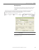
CGCM Unit Data Tables
The tables in this section show the content and organization of the CGCM Unit
data tables.
Terms
These terms are used in the following tables:
• Spare - Unused now, can be available for future use. If read, spares are zero
value. If written, spare data is ignored by the CGCM unit.
• Reserved - Used internally by CGCM unit. If read, reserve data can be any
value. If written, reserved data is ignored by the CGCM unit.
• Generator - Generator output point.
• Bus - Indicates the synchronizing reference point.
• Bus A - Indicates either a three phase reference bus, or the first single phase
reference bus.
• Bus B - If used, the second single phase reference bus.
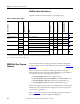
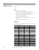
Abbreviations
The standard abbreviations shown below are used in the data table names for the
assembly object table data names.
Abbreviation Definition Abbreviation Definition
Ack Acknowledge Lo Low
Aux Auxiliary LS Load Share
Avg Average Max Maximum
AVR Automatic Voltage
Regulator
Med Medium
Brkr Breaker Min Minimum
CCC Cross Current
Compensation
OEL Over-excitation Limiting
CCCT Cross Current
Compensation
Transformer
Out Output
Comp Compensation Ovr Over
Config Configuration PF Power Factor
CT Current Transformer Ph Phase
Dly Delay PMG Permanent Magnet
Generator
En Enable Pri Primary
Ened Enabled PU Per Unit
Err Error Pwr Power
Exc Excitation Rcvd Received
FCR Field Current Regulator Redndt Redundant
Flt Fault Resvd Reserved
Freq Frequency Rev Reverse
FS Full Scale Rot Rotation
Gen Generator Sec Secondary