
Manual

16 Rockwell Automation Publication 1407-UM001G-EN-P - April 2013
Chapter 2 Installation
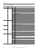
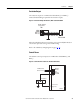
TB3
2.6…2.1 mm
2
(10…12 AWG)
ID(+)1 A 1 A cross-current compensation CT input
ID(+)5 A 5 A cross-current compensation CT input
ID(-) Cross-current compensation CT common input
I3(+)1 A 1 A phase C CT input
I3(+)5 A 5 A phase C CT input
I3(-) Phase C CT common input
I2(+)1 A 1 A phase B CT input
I2(+)5 A 5 A phase B CT input
I2(-) Phase B CT common input
I1(+)1 A 1 A phase A CT input
I1(+)5 A 1 A phase A CT input
I1(-) Phase A CT common input
TB4
1.6…1.0 mm
2
(14…18 AWG)
BAT(+) 24V DC control power input
BAT(-) 24V DC control power return
FLT Open collector fault output
RD RLY Open collector output for redundancy relay
CH GND Chassis ground
TB5 V Gen A Phase A generator voltage input
V Gen B Phase B generator voltage input
V Gen C Phase C generator voltage input
V Gen N Neutral generator voltage input
TB6 V Bus A
Phase A bus voltage input
(1)
V Bus B
Phase B bus voltage input
(1)
V Bus C Phase C bus voltage input
V Bus N Neutral bus voltage input
TB7
1.6…1.0 mm
2
(14…18 AWG)
VREF(+) Remote setpoint adjust input
VREF(-) Remote setpoint adjust input return
SHLD3 Shield 3 landing points are tied together but are not connected internally to protective earth or
other unit circuitry
SHLD3
A-COM Analog common
EX-D(+) Excitation enable input
EX-D(-) Excitation enable return
LS(+) Real power load sharing input
LS(-) Real power load sharing return
SHLD4 Shield 4 landing point is not connected internally to protective earth or other unit circuitry
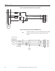
(1) When used in a dual breaker configuration, Bus A voltage input is wired from V Bus A to V Bus N and Bus B is wired from V Bus B to V Bus N.
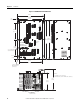
Table 1 - Terminal Block Label Description
Terminal Block Wire Gauge
Range
Label Description