
Manual

162 Rockwell Automation Publication 1407-UM001G-EN-P - April 2013
Chapter 7 Troubleshooting
Communication
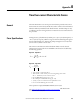
The ControlNet Network Status indicators indicate the state of the ControlNet
network connected to the BNC connectors. If more than one state is present, the
status indicators always reflect the highest priority status present on the network.
The following table describes the status indicator states and the priority of each
status indicator.
Redundancy
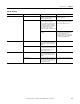
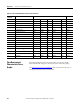
Table 31 - ControlNet A and ControlNet B Status
Status Indicator
State
Priority How to View Cause
Both steady off 1 (highest) View together Reset or no power
Both steady red 2 Failed to link interface to
ControlNet network
Alternating red and
green
3 Self testing
Alternating red 4 Bad node configuration (such as
duplicate ControlNet network
address)
Steady off 5 View independently Channel disabled or not supported
Flashing red and green 6 Invalid link configuration
Flashing red 7 Link fault or no frames received
Flashing green 8 Temporary channel error or listen
only
Steady green 9 (lowest) Normal operation
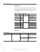
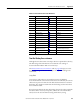
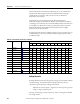
Table 32 - Redundancy
Symptom Most Likely Cause Diagnostic Action Corrective Action
Both CGCM units operate as primary
(both provide excitation to the
generator)
Serial cable not properly connected Disable excitation to one CGCM unit If excitation turns off as commanded
(one remaining CGCM operating),
repair / replace cable. If both CGCM
units continues to excite, replace
CGCM units
Connect personal computer by using
hyperterminal or similar application
to verify communication output from
CGCM unit redundancy comm port
If communication exists, see above.
If no communication output exists,
replace CGCM unit