
Manual


Rockwell Automation Publication 1407-UM001G-EN-P - April 2013 19
Installation Chapter 2
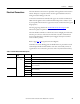
Excitation Output
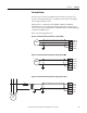
The excitation outputs are on TB2 and are labeled EXC(+) and EXC(-).
Twisted, shielded cabling is required for the excitation outputs.
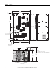
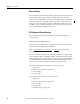
Figure 7 - Excitation Output Connections, Non-redundant CGCM
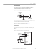
When the redundancy function is used, three or four external flyback diodes in
series must be placed across the generator field winding.
Refer to the redundancy wiring diagrams on pages 31
…32.
Control Power
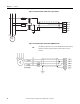
The 24V DC control power inputs are on TB4 and are labeled BAT(+) and
BAT(-).
Figure 8 - Control Power and Chassis Ground Connections
TB2
Shld2
Shld2
EXC (-)
EXC (+)
Exciter field
Exciter voltage
connections
TB4
BAT(+)
BAT(-)
FLT
RD RLY
CH GND
24 VDCControl
Power Source
Ground stud
(typical)
Ground bus
CGCM