
Manual


20 Rockwell Automation Publication 1407-UM001G-EN-P - April 2013
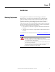
Chapter 2 Installation
Chassis
Ground
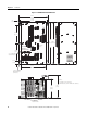
The terminal labeled CH GND, on TB4, is the chassis ground. Ground studs are
also provided on the lower part of the mounting flanges and are internally
connected to the CH GND terminal. Connect chassis ground to earth ground
with minimum 2.6 mm
2
(10 AWG) copper wire attached to either stud on the
lower part of either side of the unit and to the CH GND terminal with 1.6 mm
2
(14 AWG) copper wire. When installed in a system with other CGCM units, use
a separate lead to the ground bus from each unit.
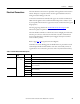
AC Voltage and Current Sensing
The CGCM unit supports generator and bus voltage sensing and generator
current sensing.
Generator and Bus Voltage Sensing
CGCM units accept single-phase or 3-phase generator and bus voltage sensing
input with nominal voltages of 120 or 208V AC.
Refer to Terminal Block Label Description
on page 15 for possible wiring
configurations.
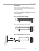
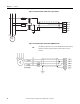
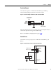
The terminals found on TB5 provide connections for generator voltage sensing
and are labeled V GEN A, V GEN B, V GEN C, and V GEN N. The terminals
found on TB6 provide connections for bus voltage sensing and are labeled V BUS
A, V BUS B, V BUS C, and V BUS N. The connection examples below show
typical connections for various generator and bus connection schemes.
The CGCM unit supports these generator connection schemes:
• Single-phase
• Delta or Two-transformer Open Delta
• Three-wire Wye
• Four-wire Wye
The CGCM supports these bus connection schemes:
• Single-phase
• Delta or Two-transformer Open Delta
• Three-wire Wye
• Four-wire Wye
• Dual Breaker, Single-phase only