
Manual

32 Rockwell Automation Publication 1407-UM001G-EN-P - April 2013
Chapter 2 Installation
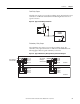
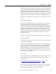
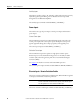
Figure 20 - Typical Redundancy Current Sensing Connection Diagram
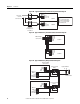
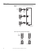
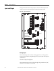
Figure 21 - Typical Redundancy Excitation Power Connection Diagram
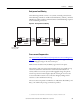
Figure 22 - Typical Redundancy Relay Connection Diagram
TB3
I1 (+) 1A
I1 (-)
I1 (+) 5A
TB 3
I1 (+) 1A
I1 (-)
I1 (+) 5A
Generator
Current
Connections
CGCM 1
CGCM 2
Typical connection for
one current input. Other
current inputs (including
the cross-current input)
should duplicate.
Customer
Supplied CT
Shorting Blocks
or Test Block
TB1
TB 1
PMG A
PMG B
PMG C
PMG Voltage
Connections
Shield
Shield
PMG A
PMG B
PMG C
Shield
Shield
CGCM 1
CGCM 2
CGCM 1
CGCM 2
TB 2
Shld2
Shld2
EXC (-)
EXC (+)
TB 2
Exciter Voltage
Connections
Shld2
Shld2
EXC (-)
EXC (+)
TB4
TB4
BAT (+)
BAT(-)
FLT
RD RLY
CH GND
BAT(+)
BAT (-)
FLT
RD RLY
CH GND
User-provided
Relay
Exciter Field
Flyback Diodes
(3 - 4)
User-provided
Relay