
Manual

Rockwell Automation Publication 1407-UM001G-EN-P - April 2013 35
Installation Chapter 2
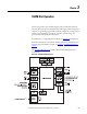
Communication Connectors and Settings
There are three ports on the unit: the factory calibration port, the redundancy
port (COM1), and the ControlNet network port.
Factory Calibration Port
The factory calibration port is not intended for use by anyone other than
qualified factory representatives.
Redundancy Port (COM1)
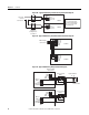
The DB-9 female connector on the bottom side of the CGCM unit is used for
communication with another CGCM unit when operating in a redundant
system configuration. Use a null modem cable for this connection.
See
CGCM Unit Interconnection Cable table for connector pin numbers,
functions, names, and signal directions.
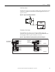
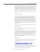
The cable pin-out is illustrated in the CGCM Unit Interconnection Cable
Diagram.
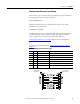
Figure 26 - CGCM Unit Interconnection Cable Diagram
Table 2 - CGCM Unit Interconnection Cable
Pin Name Description Function
1 Not used
2 XMIT Transmit Sends serial data from CGCM unit
3 RCV Receive Receives serial data from CGCM unit
4 DTR Data terminal ready Receives a signal that the sending unit is operational
5 GND Ground Provides the ground signal
6 DSR Data set ready Sends a signal that the CGCM unit is operational
7, 8, 9 Not used
To CGCM Unit
DB-9 Female
To CGCM Unit
DB-9 Female