
Manual


8 Publication ICM-UM001C-EN-E - March 2013
Chapter 1 Introduction
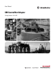
Hardware Components
The 1440-ACNR consists of the following hardware components.
Item Component Description
1 ControlNet Adapter Module
2 Status Indicators Four LEDs that indicate the status of the
adapter, backplane, and the network.
3A Channel A Coax Receptacle Channel A BNC connection.
3B Channel B Coax Receptacle Channel B BNC connection.
4 Module Locking tab
5 ControlNet Node Address
Switches
Pushwheel switches for setting the node
address. Refer to Set the Node Address on
page 15.
6 Network Access Port (NAP) Provides a bidirectional electrical interface for
programming, maintenance, and I/O monitoring
devices. Refer to the ControlNet Coax Media
Planning and Installation Guide, publication
CNET-IN002
.
7 24V DC Connections +V DC power connections.
8 24V Common Connections -V common connections.
9 XM Bus Connector Connects the adapter to the XM modules on
the XM Bus.
31770-M
1
2
3A
3B
6
4
5
8
9
7
Cont r olNet XM Adapter
1440-ACNR
XM
®
MS
CHA
CHB
BPS