Installation Instructions XM-441 Expansion Relay Module Catalog Number 1440-REX00-04RD EXPANSION RELA Y 1440-REX00-04 RD Topic Page Environment and Enclosure 3 European Hazardous Location Approval 4 North American Hazardous Location Approval 5 Mount the Module 6 Module Indicators 8 Specifications 9 Additional Resources 11
XM-441 Expansion Relay Module Important User Information Read this document and the documents listed in the additional resources section about installation, configuration, and operation of this equipment before you install, configure, operate, or maintain this product. Users are required to familiarize themselves with installation and wiring instructions in addition to requirements of all applicable codes, laws, and standards.
XM-441 Expansion Relay Module Environment and Enclosure ATTENTION: This equipment is intended for use in a Pollution Degree 2 industrial environment, in overvoltage Category II applications (as defined in IEC 60664-1), at altitudes up to 2000 m (6562 ft) without derating. This equipment is not intended for use in residential environments and may not provide adequate protection to radio communication services in such environments. This equipment is supplied as open-type equipment.
XM-441 Expansion Relay Module ATTENTION: This module is designed so you can remove and insert it under power. However, when you remove or insert the module with power applied, I/O attached to the module can change states due to its input/output signal changing conditions. Take special care when using this feature: • The serial communication port is intended only for temporary local-programming purposes and not intended for permanent connection. The serial cable and power connections are not to exceed 3.
XM-441 Expansion Relay Module North American Hazardous Location Approval The following information applies when operating this equipment in hazardous locations. Informations sur l’utilisation de cet équipement en environnements dangereux. Products marked "CL I, DIV 2, GP A, B, C, D" are suitable for use in Class I Division 2 Groups A, B, C, D, Hazardous Locations and nonhazardous locations only.
XM-441 Expansion Relay Module WARNING: The installation of the XM-441 module includes the following warnings: • When you insert or remove the module while power is on, an electrical arc can occur. This could cause an explosion in hazardous location installations. Be sure that power is removed or the area is nonhazardous before proceeding. • If you connect or disconnect the serial cable with power applied to this module or the serial device on the other end of the cable, an electrical arc can occur.
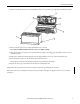
XM-441 Expansion Relay Module 1. Make certain the keyswitch (A) on the terminal base unit (C) is at position 3 as required for the XM-441 module. 2. Make certain the side connector (B) is pushed all the way to the left. You cannot install the module unless the connector is fully extended. 3. Make sure that the pins on the bottom of the module are straight so they align properly with the connector in the terminal base unit. 4.
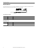
XM-441 Expansion Relay Module Module Indicators The XM-441 module has a power status indicator (PWR) that is on when power is applied to the module and a status indicator for each relay (four in all). The indicators are on top of the module. 1440-REX00-04RD EXPANSION RELAY Module Indicators Power (PWR) Status Indicator Color State Description No color Off No power applied to the module. Green Solid Power applied to the module.
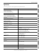
XM-441 Expansion Relay Module Specifications The following table lists the technical specifications for the XM-441 module.
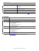
XM-441 Expansion Relay Module Attribute Wiring category XM-441 (1) 2 - on relay, power, and signal ports 3 - on Serial ports 2 - on XMbus ports Wire type Signal connections: shielded Power and Relay connections: unshielded Pilot duty rating Relay ports: Not rated North American temp code T4A IEC temp code T4 (1) Use this Conductor Category information for planning conductor routing. Refer to Industrial Automation Wiring and Grounding Guidelines, publication 1770-4.1.
XM-441 Expansion Relay Module Additional Resources For more information on the products described in this publication, use these resources. Resource Description 1440 XM Monitoring Modules Specifications Technical Data, publication 1440-TD001 Provides technical specifications for the 1440 series of monitoring modules. XM-441 Expansion Relay Module User Guide, publication GMSI10-UM019 Provides installation information and technical specifications for the XM-441 Expansion Relay Module.
Rockwell Automation Support Rockwell Automation provides technical information on the Web to assist you in using its products. At http://www.rockwellautomation.com/support you can find technical and application notes, sample code, and links to software service packs. You can also visit our Support Center at https://rockwellautomation.custhelp.com/ for software updates, support chats and forums, technical information, FAQs, and to sign up for product notification updates.