User Guide Firmware Revision 5 XM-441 Expansion Relay Module Catalog Numbers 1440- REX00-04RD
Important User Information Solid-state equipment has operational characteristics differing from those of electromechanical equipment. Safety Guidelines for the Application, Installation and Maintenance of Solid State Controls (publication SGI-1.1 available from your local Rockwell Automation sales office or online at http://www.rockwellautomation.com/literature/) describes some important differences between solid-state equipment and hard-wired electromechanical devices.
Safety Approvals The following information applies when operating this equipment in hazardous locations. Informations sur l’utilisation de cet équipement en environnements dangereux. Products marked "CL I, DIV 2, GP A, B, C, D" are suitable for use in Class I Division 2 Groups A, B, C, D, Hazardous Locations and nonhazardous locations only. Each product is supplied with markings on the rating nameplate indicating the hazardous location temperature code.
Rockwell Automation Publication GMSI10-UM019C-EN-P - June 2011
Table of Contents Chapter 1 Introducing the XM-441 Expansion Relay Module . . . . . . . . . . . . . . . . 7 XM-441 Module Components. . . . . . . . . . . . . . . . . . . . . . . . . . . . . . . . . 8 Using this Manual. . . . . . . . . . . . . . . . . . . . . . . . . . . . . . . . . . . . . . . . . . . 8 Organization. . . . . . . . . . . . . . . . . . . . . . . . . . . . . . . . . . . . . . . . . . . . 9 Document Conventions . . . . . . . . . . . . . . . . . . . . . . . . . . . . . . . . . .
Table of Contents Rockwell Automation Publication GMSI10-UM019C-EN-P - June 2011
Chapter 1 Introduction This chapter provides an overview of the XM-441 Expansion Relay module. It also discusses the components of the module. For information about Introducing the XM-441 Expansion Relay Module See page Introducing the XM-441 Expansion Relay Module 7 XM-441 Module Components 8 Using this Manual 8 The XM-441 Expansion Relay module provides an additional four relays to any XM measurement module or to the XM-440 Master Relay module.
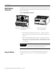
Introduction XM-441 Module Components The XM-441 consists of a terminal base unit and an instrument module. The XM-441 Expansion Relay Module and the XM-943 Expansion Relay Terminal Base are shown below. Figure 1.1 XM-441 Module Components EXPANSION RELAY XM-943 Expansion Relay Module Terminal Base Unit Cat. No. 1440-TB-D 1440-REX00-04R D XM-441 Expansion Relay Module Cat. No.
Introduction 9 Organization To help you navigate through this manual, it is organized in chapters based on these tasks and topics. Chapter 1 “Introduction” contains an overview of this manual and the XM-441 module Chapter 2 “Installing the XM-441 Expansion Relay Module” describes how to install, wire, and use the XM-441 module. Appendix A “Specifications” lists the technical specifications for the XM-441 module. For definitions of terms used in this Guide, see the Glossary at the end of the Guide.
Introduction Rockwell Automation Publication GMSI10-UM019C-EN-P - June 2011
Chapter 2 Installing the XM-441 Expansion Relay Module This chapter discusses how to install and wire the XM-441 Expansion Relay module. It also describes the module indicators and the basic operations of the module.
Installing the XM-441 Expansion Relay Module XM Installation Requirements This section describes wire, power and grounding requirements for an XM system. Wiring Requirements Use solid or stranded wire. All wiring should meet the following requirements: • 14 to 22 AWG copper conductors without pretreatment; 8 AWG required for grounding the DIN rail for electromagnetic interference (emi) purposes • Recommended strip length 8 millimeters (0.
Installing the XM-441 Expansion Relay Module IMPORTANT 13 Power connections are not made directly to the XM-441 module. Rather power is passed via the side connector from the Expansion Module's host module. Refer to that module's User Manual for further details on power requirements. Grounding Requirements Use these grounding requirements to ensure safe electrical operating circumstances, and to help avoid potential emi and ground noise that can cause unfavorable operating conditions for your XM system.
Installing the XM-441 Expansion Relay Module Figure 2.
Installing the XM-441 Expansion Relay Module 15 Figure 2.2 DIN Rail Grounding Block Panel/Wall Mount Grounding The XM modules can also be mounted to a conductive mounting plate that is grounded. See Figure 2.4. Use the grounding screw hole provided on the terminal base to connect the mounting plate the Chassis terminals. Figure 2.
Installing the XM-441 Expansion Relay Module Figure 2.4 Panel/Wall Mount Grounding 1 Power Supply 1 Power Supply 1 Mounting the Terminal Base Unit Use 14 AWG wire. The XM family includes several different terminal base units to serve all of the XM modules. The XM-943 terminal base, Cat. No. 1440-TB-D, is the only terminal base unit used with the XM-441.
Installing the XM-441 Expansion Relay Module 17 The terminal base can be DIN rail or wall/panel mounted. Refer to the specific method of mounting below. ATTENTION The XM modules make a chassis ground connection through the DIN rail. Use zinc plated, yellow chromated steel DIN rail to assure proper grounding. Using other DIN rail materials (e.g. aluminum, plastic, etc.), which can corrode, oxidize or are poor conductors can result in improper or intermittent platform grounding.
Installing the XM-441 Expansion Relay Module 3. Slide the terminal base unit over tight against the neighboring terminal base. Make sure the hook on the terminal base slides under the edge of the adjacent base and the side connector is fully retracted. 4. Rotate the terminal base onto the DIN rail with the top of the rail hooked under the lip on the rear of the terminal base. 5. Press down on the terminal base unit to lock the terminal base on the DIN rail.
Installing the XM-441 Expansion Relay Module 19 1. Lay out the required points on the wall/panel as shown in the drilling dimension drawing below. Side Connector 2. Drill the necessary holes for the #6 self-tapping mounting screws. 3. Retract the side connector into the base unit. Make sure it is fully retracted. 4. Position the terminal base unit up tight against the neighboring terminal base. Make sure the hook on the terminal base slides under the edge of the terminal base unit. 5.
Installing the XM-441 Expansion Relay Module Figure 2.5 XM-942 Terminal Base Unit XM-943, Cat. No. 1440-TB-D Terminal Block Assignments The terminal block assignments and descriptions for the XM-441 module are shown below. ATTENTION WARNING The terminal block assignments are different for different XM modules. The following table applies only to the XM-441. Refer to the installation instructions for the specific XM module for its terminal assignments.
Installing the XM-441 Expansion Relay Module 21 Terminal Assignments No. Name Description 8 Relay 2 N.O. 1 Relay # 2 Normally Open contact 1 9 Relay 3 N.O. 2 Relay #3 Normally Open contact 2 10 No Connection 11 Relay 3 N.O. 1 Relay #3 Normally Open contact 1 12 Relay 4 N.O. 2 Relay #4 Normally Open contact 2 13 Relay 4 N.O.
Installing the XM-441 Expansion Relay Module Terminal Assignments No. Name Description 43 Relay 3 N.C. 2 Relay #3 Normally Closed contact 2 44 No Connection 45 Relay 3 N.C. 1 Relay #3 Normally Closed contact 1 46 Relay 4 N.C. 2 Relay #4 Normally Closed contact 2 47 Relay 4 N.C.
Installing the XM-441 Expansion Relay Module 23 There are four double pole double throw relays in the XM-441. All relay contacts (24 total) are available for wiring at the terminal base unit, as shown in Table 2.1 on the page 23. All XM relays are double pole. This means that each relay has two contacts in which each contact operates independently but identically.
Installing the XM-441 Expansion Relay Module Figure 2.6 Relay Connection - Failsafe, Nonalarm Condition Non-failsafe, Alarm Condition Figure 2.7 Relay Connection - Failsafe Alarm Condition Non-failsafe, Nonalarm Condition Alternate Relay Wiring Figures 2.8 and 2.9 show how to wire both ends of a single external indicator to the XM terminal base for failsafe, nonalarm or alarm condition or non-failsafe, nonalarm or alarm condition. Figure 2.
Installing the XM-441 Expansion Relay Module 25 Figure 2.9 Relay Connection - Failsafe, Alarm Condition Non-failsafe, Alarm Condition Mounting the Module The XM-441 mounts on the XM-943 terminal base unit, Cat. No. 1440-TB-D. You should mount the module after you have connected the wiring on the terminal base unit. ATTENTION The XM-441 is compatible only with the XM-943 terminal base unit. The keyswitch on the terminal base unit should be at position 3 for the XM-441.
Installing the XM-441 Expansion Relay Module 1. Make certain the keyswitch (A) on the terminal base unit (C) is at position 3 as required for the XM-441. 2. Make certain the side connector (B) is pushed all the way to the left. You cannot install the module unless the connector is fully extended. 3. Make sure that the pins on the bottom of the module are straight so they will align properly with the connector in the terminal base unit. 4.
Installing the XM-441 Expansion Relay Module Figure 2.10 LED Indicators 1440-REX00-04RD EXPANSION RELAY Module Indicators The following tables describe the states of the LED status indicators. Power Status Indicator Color State Description No color Off No power applied to the module. Green Solid Power applied to the module. Relay Indicators (4 in all) Color State Description Red Off On-board relay is not activated. Solid On-board relay is activated.
Installing the XM-441 Expansion Relay Module Rockwell Automation Publication GMSI10-UM019C-EN-P - June 2011
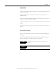
Appendix A Specifications The Appendix lists the technical specifications for the XM-441 module. XM-441 Technical Specifications Product Feature Specification Communications Communication interface is via the side connector between the XM-441 and the XM module mounted directly to the left of the XM-441. Side Connector All XM measurement and relay modules include side connectors that allow interconnecting adjacent modules, thereby simplifying the external wiring requirements.
Specifications XM-441 Technical Specifications Product Feature Specification Power Module 24V DC Consumption 120mA maximum Heat Production 2.9 Watts (9.9 BTU/hr) maximum Environmental Operating Temperature -20 to +65°C (-4 to +149°F) Storage Temperature -40 to +85°C (-40 to +185°F) Relative Humidity 95% non-condensing All printed circuit boards are conformally coated in accordance with IPC-A-610C, Physical Dimensions Height: 3.8in (97mm) Width: 3.7in (94mm) Depth: 3.
Glossary alarm An alarm alerts you to a change in a measurement. For example, an alarm can notify you when the measured vibration level for a machine exceeds a pre-defined value. Automatic Device Replacement (ADR) A means for replacing a malfunctioning device with a new unit, and having the device configuration data set automatically. The ADR scanner uploads and stores a device’s configuration.
Glossary current configuration The current configuration is the most recently loaded set of configuration parameters in the XM module’s memory. When power is cycled, the current configuration is loaded with either the saved configuration (in EEPROM) or the factory defaults (if there is no saved configuration). In addition, the current configuration contains any configuration changes that have been downloaded to the module since power was applied.
Glossary 33 master device A device which controls one or more slave devices. The XM-440 Master Relay module is a master device. node address A DeviceNet network can have as many as 64 devices connected to it. Each device on the network must have a unique node address between 0 and 63. Node address 63 is the default used by uncommissioned devices. Node address is sometimes called “MAC ID.” NVS (Non-Volatile Storage) NVS is the permanent memory of an XM module.
Glossary XM Serial Configuration Utility Software XM Serial Configuration Utility software is a tool for monitoring and configuring XM modules. It can be run on computers running Windows 2000 service pack 2, Windows NT service pack 6, or Windows XP operating systems.
Index C P components terminal base XM-943 8 XM-441 Expansion Relay module 8 connecting wiring 19 relays 22 terminal base XM-943 19 D description terminal base XM-943 8 XM-441 module 8 DIN Rail Grounding Block 14 DIN rail grounding requirements 13 document conventions 9 panel/wall mount grounding requirements 15 power requirements 12 Power Status indicator 27 R relay contacts normally closed 22 normally open 22 relay indicators 27 relays, wiring 22 S specifications 29 T G terminal base mounting on
Index Rockwell Automation Publication GMSI10-UM019C-EN-P - June 2011
Rockwell Automation Support Rockwell Automation provides technical information on the Web to assist you in using its products. At http://www.rockwellautomation.com/support/, you can find technical manuals, a knowledge base of FAQs, technical and application notes, sample code and links to software service packs, and a MySupport feature that you can customize to make the best use of these tools.