
User guide


Rockwell Automation Publication GMSI10-UM019C-EN-P - June 2011
Installing the XM-441 Expansion Relay Module 23
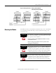
There are four double pole double throw relays in the XM-441. All relay
contacts (24 total) are available for wiring at the terminal base unit, as shown in
Table 2.1 on the page 23.
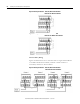
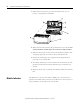
Figures 2.6 and 2.7 illustrate the behavior of the NC and NO terminals when
the relay is wired for failsafe, alarm or nonalarm condition or non-failsafe,
alarm or nonalarm condition.
IMPORTANT
All XM relays are double pole. This means that each relay
has two contacts in which each contact operates
independently but identically. The following information
and illustrations show wiring solutions for both contacts;
although, in many applications it may be necessary to wire
only one contact.
IMPORTANT
The NC/NO terminal descriptions (pages 20–22)
correspond to a de-energized (unpowered) relay.
When the relay is configured for non-failsafe operation, the
relay is normally de-energized.
When the relay is configured for failsafe operation, the
relay is normally energized, and the behavior of the NC and
NO terminals is inverted.
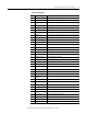
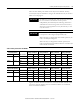
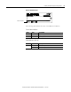
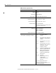
Table 2.1 Relay Connections for XM-441
Configured for
Failsafe Operation Relay 1 Terminals Relay 2 Terminals Relay 3 Terminals Relay 4 Terminals
Nonalarm Alarm Wire Contacts Contact 1 Contact 2 Contact 1 Contact 2 Contact 1 Contact 2 Contact 1 Contact 2
Closed Opened COM 21 20 24 22 27 25 29 28
NO 5 4 8 6 11 9 13 12
Opened Closed COM 21 20 24 22 27 25 29 28
NC 39 38 42 40 45 43 47 46
Configured for
Non-failsafe Operation Relay 1 Terminals Relay 2 Terminals Relay 3 Terminals Relay 4 Terminals
Nonalarm Alarm Wire Contacts Contact 1 Contact 2 Contact 1 Contact 2 Contact 1 Contact 2 Contact 1 Contact 2
Closed Opened COM 21 20 24 22 27 25 29 28
NC 39 38 42 40 45 43 47 46
Opened Closed COM 21 20 24 22 27 25 29 28
NO 5 4 8 6 11 9 13 12