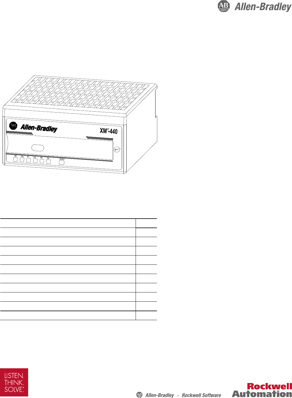
Installation Instructions XM-440 Master Relay Module Catalog Number 1440-RMA00-04RC MASTER RELA Y 1440-RMA00-0 4RC Topic Page Environment and Enclosure 3 European Hazardous Location Approval 4 North American Hazardous Location Approval 5 Mount the Module 6 Module Indicators 7 Self-Test 8 Reset Switch 8 Install the XM Serial Configuration Utility Software 9 Specifications 10 Additional Resources 12
XM-440 Master Relay Module Important User Information Read this document and the documents listed in the additional resources section about installation, configuration, and operation of this equipment before you install, configure, operate, or maintain this product. Users are required to familiarize themselves with installation and wiring instructions in addition to requirements of all applicable codes, laws, and standards.
XM-440 Master Relay Module Environment and Enclosure ATTENTION: This equipment is intended for use in a Pollution Degree 2 industrial environment, in overvoltage Category II applications (as defined in IEC 60664-1), at altitudes up to 2000 m (6562 ft) without derating. This equipment is not intended for use in residential environments and may not provide adequate protection to radio communication services in such environments. This equipment is supplied as open-type equipment.
XM-440 Master Relay Module ATTENTION: The serial communication port is intended only for temporary local-programming purposes and not intended for permanent connection. The serial cable and power connections are not to exceed 3.0 m (9.84 ft): • This product is intended to be mounted to a well-grounded mounting surface, such as a metal panel or DIN rail. For DIN rail mounting, use zinc plated yellow-chromate steel DIN rail to assure proper grounding.
XM-440 Master Relay Module North American Hazardous Location Approval The following information applies when operating this equipment in hazardous locations: Informations sur l'utilisation de cet équipement en environnements dangereux. Products marked "CL I, DIV 2, GP A, B, C, D" are suitable for use in Class I Division 2 Groups A, B, C, D, Hazardous Locations and nonhazardous locations only.
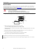
XM-440 Master Relay Module Mount the Module The XM® 440 module mounts on a XM-942 terminal base unit, catalog number 1440-TB-C. We recommend that you mount the module after you have connected the wiring on the terminal base unit. Refer to the XM-942 Master Relay Terminal Base Installation Instructions, publication GMSI10-IN022. The XM-440 module is compatible only with the XM-942 terminal base unit. Verify that the keyswitch on the terminal base unit is at position 2 for the XM-440 module.
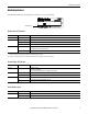
XM-440 Master Relay Module Module Indicators The XM-440 module has six status indicators, which are on top of the module. 1440-RMA00-04RC MASTER RELAY Module Indicators Module Status (MS) Indicator Color State Description No color Off No power applied to the module. Green Flashing red Module performing power-up self-test. Flashing Module operating in Program mode.(1) Solid Module operating in Run mode.(2) Flashing • Application firmware is invalid or not loaded.
XM-440 Master Relay Module Self-Test The XM-440 module performs a self-test at powerup. The self-test includes a status indicator test and a device test. During the status indicator test, the indicators are turned on independently and in sequence for approximately 0.25 seconds. The device test occurs after the status indicator test. The Module Status (MS) indicator is used to indicate the status of the device self-test.
XM-440 Master Relay Module Install the XM Serial Configuration Utility Software The XM Documentation and Configuration Utility CD is packaged with the XM modules. It contains the XM Serial Configuration Utility software, a set of user guides, hazardous location installation drawings, and electronic data sheet (EDS) files that are used by network configuration tools such as RSNetWorx™ for DeviceNet software.
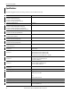
XM-440 Master Relay Module Specifications The following table lists the technical specifications for the XM-440 module.
XM-440 Master Relay Module Attribute Wiring category XM-440 (1) 2 - on relay and shielded signal ports 3 - on Serial and power ports 2 - on XMbus ports Wire type Signal connections: shielded Power and relay connections: unshielded Pilot duty rating Relay ports: Not rated North American temp code T4A IEC temp code T4 (1) Use this Conductor Category information for planning conductor routing. Refer to Industrial Automation Wiring and Grounding Guidelines, publication 1770-4.1.
Additional Resources For more information on the products described in this publication, use these resources. Resource Description 1440 XM Monitoring Modules Specifications Technical Data, publication 1440-TD001 Provides technical specifications for the 1440 series of monitoring modules.