User Guide Firmware Revision 5 XM-440 Master Relay Module Catalog Numbers 1440-RMA00-04RC
Important User Information Solid-state equipment has operational characteristics differing from those of electromechanical equipment. Safety Guidelines for the Application, Installation and Maintenance of Solid State Controls (publication SGI-1.1 available from your local Rockwell Automation sales office or online at http://www.rockwellautomation.com/literature/) describes some important differences between solid-state equipment and hard-wired electromechanical devices.
Safety Approvals The following information applies when operating this equipment in hazardous locations. Informations sur l’utilisation de cet équipement en environnements dangereux. Products marked "CL I, DIV 2, GP A, B, C, D" are suitable for use in Class I Division 2 Groups A, B, C, D, Hazardous Locations and nonhazardous locations only. Each product is supplied with markings on the rating nameplate indicating the hazardous location temperature code.
Rockwell Automation Publication GMSI10-UM009D-EN-P - June 2011
Table of Contents Chapter 1 Introduction Introducing the XM-440 Relay Module . . . . . . . . . . . . . . . . . . . . . . . . . 9 XM-440 Module Components. . . . . . . . . . . . . . . . . . . . . . . . . . . . . . . . 10 Using this Manual. . . . . . . . . . . . . . . . . . . . . . . . . . . . . . . . . . . . . . . . . . 10 Organization. . . . . . . . . . . . . . . . . . . . . . . . . . . . . . . . . . . . . . . . . . . 11 Document Conventions . . . . . . . . . . . . . . . . . . . . . . . . . . . . . . . . .
Table of Contents XM Services . . . . . . . . . . . . . . . . . . . . . . . . . . . . . . . . . . . . . . . . . . . . . . 59 Invalid Configuration Errors . . . . . . . . . . . . . . . . . . . . . . . . . . . . . . . . . 60 XM-440 I/O Message Formats . . . . . . . . . . . . . . . . . . . . . . . . . . . . . . . 61 COS Message Format . . . . . . . . . . . . . . . . . . . . . . . . . . . . . . . . . . . 61 XM Status Values. . . . . . . . . . . . . . . . . . . . . . . . . . . . . . . . . . . . . . .
Table of Contents 7 Entek Log Object (Class ID 321H) . . . . . . . . . . . . . . . . . . . . . . . . . . . . . . . . . . . . . . . . . . . 82 Class Attributes . . . . . . . . . . . . . . . . . . . . . . . . . . . . . . . . . . . . . . . . 82 Instance Attributes. . . . . . . . . . . . . . . . . . . . . . . . . . . . . . . . . . . . . . 83 Services . . . . . . . . . . . . . . . . . . . . . . . . . . . . . . . . . . . . . . . . . . . . . . . 83 Get_Event Service Request Data Format . . . . . . . . . . . . .
Table of Contents Rockwell Automation Publication GMSI10-UM009D-EN-P - June 2011
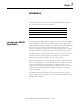
Chapter 1 Introduction This chapter provides an overview of the XM-440 Master Relay module. It also discusses the components of the module. For information about Introducing the XM-440 Relay Module See page Introducing the XM-440 Relay Module 9 XM-440 Module Components 10 Using this Manual 10 The XM-440 Master Relay module combines four relay outputs with XM bus master capabilities to provide remote, shared, and voted relay operation for distributed XM measurement modules.
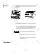
Introduction XM-440 Module Components The XM-440 consists of a terminal base unit and an instrument module. The XM-440 Master Relay Module and the XM-942 Master Relay Terminal Base are shown below. Figure 1.1 XM-440 Module Components MASTER RELAY XM-942 Master Relay Module Terminal Base Unit Cat. No. 1440-TB-C 1440-RMA00-04R C XM-440 Master Relay Module Cat. No.
Introduction 11 Organization To help you navigate through this manual, it is organized in chapters based on these tasks and topics. Chapter 1 “Introduction” contains an overview of this manual and the XM-440 module. Chapter 2 “Installing the XM-440 Relay Module” describes how to install, wire, and use the XM-440 module. Chapter 3 “Configuration Parameters” provides a complete listing and description of the XM-440 parameters.
Introduction Rockwell Automation Publication GMSI10-UM009D-EN-P - June 2011
Chapter 2 Installing the XM-440 Master Relay Module This chapter discusses how to install and wire the XM-440 Master Relay Module. It also describes the module indicators and the basic operations of the module.
Installing the XM-440 Master Relay Module XM Installation Requirements This section describes wire, power and grounding requirements for an XM system. Wiring Requirements Use solid or stranded wire. All wiring should meet the following specifications: • 14 to 22 AWG copper conductors without pretreatment; 8 AWG required for grounding the DIN rail for electromagnetic interference (emi) purposes • Recommended strip length 8 millimeters (0.
Installing the XM-440 Master Relay Module Figure 2.
Installing the XM-440 Master Relay Module IMPORTANT See Application Technique "XM Power Supply Solutions", publication ICM-AP005A-EN-E, for guidance in architecting power supplies for XM systems. Grounding Requirements Use these grounding requirements to ensure safe electrical operating circumstances, and to help avoid potential emi and ground noise that can cause unfavorable operating conditions for your XM system.
Installing the XM-440 Master Relay Module Figure 2.
Installing the XM-440 Master Relay Module Figure 2.3 Grounded DIN Rail with Block Panel/Wall Mount Grounding The XM modules can also be mounted to a conductive mounting plate that is grounded. See Figure 2.5. Use the grounding screw hole provided on the terminal base to connect the mounting plate the Chassis terminals. Figure 2.
Installing the XM-440 Master Relay Module Figure 2.5 Panel/Wall Mount Grounding 1 Power Supply 1 Power Supply 1 Use 14 AWG wire.
Installing the XM-440 Master Relay Module 24V Common Grounding 24 V power to the XM modules must be grounded. When two or more power supplies power the XM system, ground the 24 V Commons at a single point, such as the ground bus bar. IMPORTANT IMPORTANT If it is not possible or practical to ground the -24Vdc supply, then it is possible for the system to be installed and operate ungrounded.
Installing the XM-440 Master Relay Module ATTENTION 21 Use of a separate DeviceNet power supply is not permitted. See Application Technique "XM Power Supply Solutions", publication ICM-AP005A-EN-E, for guidance in using XM with other DeviceNet products. For more information on the DeviceNet installation, refer to the ODVA Planning and Installation Manual - DeviceNet Cable System, which is available on the ODVA web site (http://www.odva.org).
Installing the XM-440 Master Relay Module 1. Position the terminal base on the 35 x 7.5mm DIN rail (A). Position terminal base at a slight angle and hook over the top of the DIN rail. 2. Slide the terminal base unit over leaving room for the side connector (B). 3. Rotate the terminal base onto the DIN rail with the top of the rail hooked under the lip on the rear of the terminal base. 4. Press down on the terminal base unit to lock the terminal base on the DIN rail.
Installing the XM-440 Master Relay Module 23 Interconnecting Terminal Base Units Follow the steps below to install another terminal base unit on the DIN rail. IMPORTANT Make certain you install the terminal base units in order of left to right. 1. Position the terminal base on the 35 x 7.5mm DIN rail (A). 2. Make certain the side connector (B) is fully retracted into the base unit. 3. Slide the terminal base unit over tight against the neighboring terminal base.
Installing the XM-440 Master Relay Module Use the following steps to install the terminal base on a wall or panel. 1. Lay out the required points on the wall/panel as shown in the drilling dimension drawing below. Side Connector 2. Drill the necessary holes for the #6 self-tapping mounting screws. 3. Secure the terminal base unit using two #6 self-tapping screws. 4. To install another terminal base unit, retract the side connector into the base unit. Make sure it is fully retracted. 5.
Installing the XM-440 Master Relay Module 25 Figure 2.7 XM-942 Terminal Base Unit XM-942, Cat. No. 1440-TB-C Terminal Block Assignments The terminal block assignments and descriptions for the XM-440 module are shown below. ATTENTION WARNING The terminal block assignments are different for different XM modules. The following table applies only to the XM-440. Refer to the installation instructions for the specific XM module for its terminal assignments.
Installing the XM-440 Master Relay Module Terminal Block Assignments No. Name Description 7 No Connection 8 Relay 2 N.O. 1 Relay # 2 Normally Open contact 1 9 Relay 3 N.O. 2 Relay #3 Normally Open contact 2 10 No Connection 11 Relay 3 N.O. 1 Relay #3 Normally Open contact 1 12 Relay 4 N.O. 2 Relay #4 Normally Open contact 2 13 Relay 4 N.O.
Installing the XM-440 Master Relay Module 27 Terminal Block Assignments No. Name Description 42 Relay 2 N.C. 1 Relay #2 Normally Closed contact 1 43 Relay 3 N.C. 2 Relay #3 Normally Closed contact 2 44 No Connection 45 Relay 3 N.C. 1 Relay #3 Normally Closed contact 1 46 Relay 4 N.C. 2 Relay #4 Normally Closed contact 2 47 Relay 4 N.C.
Installing the XM-440 Master Relay Module IMPORTANT ATTENTION 24Vdc needs to be wired to terminal 0 (+24 V In) to provide power to the device and other XM modules linked to the wired terminal base via the side connector. The power connections are different for different XM modules. Refer to the installation instructions for your specific XM module for complete wiring information. Connecting the Relays The XM-440 has both Normally Open (NO) and Normally Closed (NC) relay contacts.
Installing the XM-440 Master Relay Module IMPORTANT T 29 The NC/NO terminal descriptions (pages 25–27) correspond to a de-energized (unpowered) relay. When the relay is configured for non-failsafe operation, the relay is normally de-energized. When the relay is configured for failsafe operation, the relay is normally energized, and the behavior of the NC and NO terminals is inverted.
Installing the XM-440 Master Relay Module Table 2.
Installing the XM-440 Master Relay Module 31 Figure 2.10 Relay Connection - Failsafe Alarm Condition Non-failsafe, Nonalarm Condition Alternate Relay Wiring Figures 2.11 and 2.12 show how to wire both ends of a single external indicator to the XM terminal base for failsafe, nonalarm or alarm condition or non-failsafe, nonalarm or alarm condition. Figure 2.11 Relay Connection - Failsafe, Nonalarm Condition Non-failsafe, Alarm Condition Figure 2.
Installing the XM-440 Master Relay Module Connecting the Remote Relay Reset Signal If you set the module relay to latching and the relay activates, the relay stays activated even when the condition that caused the alarm has ended. The remote relay reset signal enables you to reset your module relay remotely after you have corrected the alarm condition. This includes latched relays in the Expansion Relay module when it is attached to the XM-440..
Installing the XM-440 Master Relay Module 33 A single switch contact can also be shared by multiple XM modules wired in parallel as shown in Figure 2.14. ATTENTION The relay reset connections may be different for different XM modules. Figure 2.14 applies only to the XM-440 module. Refer to the installation instructions for the module for its terminal assignments. Figure 2.
Installing the XM-440 Master Relay Module • Mini-Connector - The mini-connector is located on the top of the XM-440, as shown below. Figure 2.15 Mini-Connector 1440-RMA00-04RC MASTER RELAY mini-connector A special cable (Cat. No. 1440-SCDB9FXM2) is required for this connection. The connector that inserts into the PC is a DB-9 female connector, and the connector that inserts into the module is a USB Mini-B male connector.
Installing the XM-440 Master Relay Module 35 Connect the DeviceNet cable to the terminal base unit as shown. Connect To Terminal Base Unit Red Wire DNet V+ 32 (Optional - see note) White Wire CAN High 33 Bare Wire Shield (Chassis) 49 Blue Wire CAN Low 51 Black Wire DNet V- 50 IMPORTANT The DeviceNet power circuit through the XM module interconnect, which is rated at only 300 mA, is not intended or designed to power DeviceNet loads. Doing so could damage the module or terminal base.
Installing the XM-440 Master Relay Module The device is shipped from the factory with the network node address (MAC ID) set to 63 and the baud rate set to “autobaud.” Both parameters are software settable. IMPORTANT At least one master device on the DeviceNet network must be set to a fixed baud rate. If the only DeviceNet master on your network is the XM-440, make certain to change its baud rate from “autobaud” to 500 kbps, 250 kbps, or 120 kbps as appropriate.
Installing the XM-440 Master Relay Module 37 1. Make certain the keyswitch (A) on the terminal base unit (C) is at position 2 as required for the XM-440. 2. Make certain the side connector (B) is pushed all the way to the left. You cannot install the module unless the connector is fully extended. 3. Make sure that the pins on the bottom of the module are straight so they will align properly with the connector in the terminal base unit. 4.
Installing the XM-440 Master Relay Module The XM-440 has six LED indicators, which include a module status (MS) indicator, a network status (NS) indicator, and a status indicator for each Relay (four in all). The LED indicators are located on top of the module. Module Indicators Figure 2.16 LED Indicators 1440-RMA00-04RC MASTER RELAY Module Indicators The following tables describe the states of the LED status indicators.
Installing the XM-440 Master Relay Module 39 Network Status (NS) Indicator Color State Description No color Off Module is not online. • Module is autobauding. • No power is applied to the module, look at Module Status LED. Green Red Flashing Module is online (DeviceNet) but no connections are currently established. Solid Module is online with connections currently established. Flashing One or more I/O connections are in the Timed-Out state.
Installing the XM-440 Master Relay Module Refer to Module Indicators on page 38 for more information about the LED indicators. Manually Resetting Relays The XM-440 has an external reset switch located on top of the module, as shown in Figure 2.17. Figure 2.17 Reset Switch 1440-RMA00-04RC MASTER RELAY Press the Reset Switch to reset the relays The switch can be used to reset all latched relays in the module. This includes the relays in the Expansion Relay Module when it is connected to the XM-440.
Chapter 3 Configuration Parameters This chapter provides a complete listing and description of the XM-440 parameters. The parameters can be viewed and edited using the XM Serial Configuration Utility software and a personal computer. If the module is installed on a DeviceNet network, configuring can also be performed using a network configuration tool such as RSNetWorx (Version 3.0 or later). Refer to your configuration tool documentation for instructions on configuring a device.
Configuration Parameters XM Network Node List Parameters Parameter Name Description Values/Comments Module Type The type of XM measurement module at this node address. Options: XM-120 XM-120E XM-121 XM-121A XM-122 XM-123 XM-160 XM-161 XM-162 XM-220 XM-320 XM-360 XM-361 XM-362 None (EDS file only) Share Option Sets the relationship between the XM-440 (master) and the XM measurement module (slave). Options: Primary Shared • Primary - The XM-440 is the primary master of the XM measurement module.
Configuration Parameters 43 XM Network Node List Parameters Parameter Name Description Values/Comments Interscan Delay Defines the amount of time the XM-440 pauses between consecutive scans. This means that the XM-440 will poll all the slaves in its scanlist, then pause for interscan delay, then begin the next series of polls. Enter a value from 2 to 9,000 milliseconds. The default is 400 milliseconds.
Configuration Parameters XM Network Node List Parameters Parameter Name Description Values/Comments Slave EPR Sets the rate at which the packets will be expected to be received by the XM-440. Enter a value from 10 to 32,000 milliseconds. The default is 200 milliseconds. When the XM-440 opens a polled I/O connection, it sets a maximum timeout (Expected Packet Rate (EPR)) with the slave.
Configuration Parameters 45 The Relay parameters control the operation of the on-board relays, as well as the relays on the Expansion Relay (XM-441) module(s). Use these parameters to configure which alarms the relays are associated with as well as the behavior of the relay. Relay Parameters IMPORTANT A relay can be defined, regardless of whether or not it is physically present. A non-physical relay is a virtual relay.
Configuration Parameters Relay Parameters Parameter Name Description Controls whether the relay must be explicitly reset after the alarm subsides. XM Configuration EDS File Utility Latching Latching Option Activation Delay Enter the length of time for which the relay activation logic (Activate relay when parameter) must be true before the relay is activated.
Configuration Parameters Relay Parameters Parameter Name Description XM Configuration EDS File Utility Failsafe Relay Failsafe Option Options/Comments Determines whether the relay is failsafe or non-failsafe. Failsafe operation means that when in alarm, the relay contacts are in their “normal,” de-energized, or “shelf-state” positions. In other words, normally closed relays are closed in alarm, and normally open relays are open in alarm. With failsafe operation, a power failure equals an alarm.
Configuration Parameters Relay Parameters Parameter Name XM Configuration EDS File Utility Input List Node Address (Module Type) Input Node Description Options/Comments The node address of the XM measurement module that maintains the alarm or relay. Notes: • In the XM Configuration Utility, the XM measurement module must be added to the XM Network Node List before it can be added to an Alarm List.
Configuration Parameters 49 • The group trigger will work only with XM measurement modules running revision 4 or later firmware. IMPORTANT The Group Triggers parameters are not included in the EDS file and cannot be edited using generic configuration tools such as RSNetWorx for DeviceNet. Group Trigger Parameters Parameter Name Description Values/Comments Group List Sets the trigger group to be configured. You can create up to four trigger groups for each XM-440 module.
Configuration Parameters Device Mode Parameters The Device Mode parameters are used to control the functions and the behavior of the device. IMPORTANT The XM Serial Configuration Utility handles these parameters automatically and transparently to the user. Device Mode Parameters Parameter Name Description Values/Comments Device Mode Sets the current operation mode of the device. Refer to Changing Operation Modes on page 57 for more information.
Configuration Parameters Event Log Parameters Parameter Name Description Node Displays the node address of the module where the event occurred. Alarm & Relay Displays the alarm or relay that changed status (if applicable). New Status Displays the new status of the alarm/relay (if applicable).
Configuration Parameters Rockwell Automation Publication GMSI10-UM009D-EN-P - June 2011
Appendix A Specifications The Appendix lists the technical specifications for the XM-440 module. XM-440 Technical Specifications Product Feature Specification Communications DeviceNet Standard DeviceNet protocol for all functions NOTE: The XM-440 uses only the DeviceNet protocol, not power. Module power is provided independently.
Specifications XM-440 Technical Specifications Product Feature Specification Relays Number Four relays, two sets of contacts each DPDT (2 Form C) Four or eight additional relays when connected to one or two XM-441 Expansion Relay modules Contacts 250V AC, 50/60 Hz, 3 A Resistive Failsafe Normally energized (failsafe), or Normally de-energized (non-fail-safe) Latching Latching, or Non-latching Time Delay 0 to 25.
Specifications 55 XM-440 Technical Specifications Product Feature Agency Certification (when product or packaging is marked) Specification UL UL Listed for Ordinary Locations UL UL Listed for Class I, Division 2 Group A, B, C, and D Hazardous Locations CSA CSA Certified Process Control Equipment CSA CSA Certified Process Control Equipment for Class I, Division 2 Group A, B, C, and D Hazardous Locations EEX* European Union 94/9/EEC ATEX Directive, compliant with EN 50021; Potentially Explosive At
Specifications Rockwell Automation Publication GMSI10-UM009D-EN-P - June 2011
Appendix B DeviceNet Information Electronic Data Sheet (EDS) files are simple text files used by network configuration tools such as RSNetWorx (Version 3.0 or later) to help you identify products and easily commission them on a network. The EDS files describe a product’s device type, product revision, and configurable parameters on a DeviceNet network. Electronic Data Sheets The EDS files for the XM modules are installed on your computer with the XM configuration software.
DeviceNet Information Transition to Program Mode Parameter values can only be downloaded to an XM module while the module is in Program mode. Any attempt to download a parameter value while the module is in Run mode will result in a Device State Conflict error. To transition an XM module from Run mode to Program mode on a DeviceNet network, set the Device Mode parameter to "Program mode" and click Apply.
DeviceNet Information The table below defines the services supported by the XM modules. The table includes the service codes, classes, instances, and attributes by their appropriate hexadecimal codes. Use the Class Instance Editor in RSNetWorx to execute these services, as illustrated in the example below.
DeviceNet Information Example To save the configuration parameters to the non-volatile memory (EEPROM), fill in the Class Instance Editor as shown below. Clear Send the attribute ID and then enter the Class (320 hex) and Instance (1) Select the Save service code Click Execute to initiate the action Invalid Configuration Errors A Start or Save service request to an XM module may return an Invalid Device Configuration error when there is a conflict amongst the configuration settings.
DeviceNet Information 61 Additional Error Codes returned with the Invalid Device Configuration Error (0xD0) XM-440 I/O Message Formats Error Code (Hex) Description 0A Too many alarms associated with a single measurement. 0B Invalid node address in the alarm list. 0C Too many alarms in the alarm list. Or, no alarms in the alarm list. 0D Alarm levels cannot be zero for alarms that are enabled. 0E Too many slaves in the scanner’s input data table.
DeviceNet Information XM Status Values The XM Status values included in the COS messages are defined in the table below. Relay Status Descriptions Relay Status Value Using RSNetWorx with the XM-440 Description 0 Not Activated 1 Activated The XM-440 acts as a DeviceNet master/scanner on the XM network. The measurement modules are slaves to the XM-440. The XM-440 is an application specific master, however.
DeviceNet Information 63 As an application specific master, the XM-440 has application specific parameters in addition to the parameters related to the scanlist. Since the Scanner applet can configure only scanlist parameters, it cannot be used to configure the XM-440. Instead, the EDS Devices applet is used, as shown below.
DeviceNet Information Configuring the XM-440 Scanlist The scanlist parameters in the XM-440 EDS file include: Module Type and Share Status for every possible node address. You must configure these parameters manually when setting up the XM-440 scanlist. To configure the Module Type Parameters 1 to 64 (Module Type group) are used to enter the module type information. You must select the XM measurement module type at each node address, or select "None" for the node addresses that are not used.
DeviceNet Information 65 To configure the Sharing Status Parameters 65 to 128 (Sharing Status group) are used to enter the share status information. Follow these guidelines when configuring the Share Option parameter. • If the XM-440 is the primary master of an XM measurement module, then the Share Option parameter for the corresponding node address must be set to "primary.
DeviceNet Information ADR for XM Modules Automatic Device Replacement (ADR) is a feature of an Allen-Bradley DeviceNet scanner. It provides a means for replacing a failed device with a new unit, and having the device configuration data set automatically. Upon replacing a failed device with a new unit, the ADR scanner automatically downloads the configuration data and sets the node address. IMPORTANT It is recommended that ADR not be used in safety related applications.
DeviceNet Information 67 • The ADR scanner saves and restores only the configuration parameters contained in the module’s EDS file. Some XM parameters are not included in the EDS file because they are not supported by either the EDS specification or the tools that read the EDS files, for example RSNetWorx for DeviceNet. These configuration parameters will not be restored with ADR.
DeviceNet Information Rockwell Automation Publication GMSI10-UM009D-EN-P - June 2011
Appendix C DeviceNet Objects Appendix C provides information on the DeviceNet objects supported by the XM-440 module.
DeviceNet Objects The Identity Object provides identification and general information about the device. Identity Object (Class ID 01H) Class Attributes The Identity Object provides no class attributes. Instance Attributes Table C.
DeviceNet Objects 71 Table C.2 Identity Object Status Bit Name Description 4 Boot Program Vendor-specific, indicates that the boot program is running. The Main Application must be corrupt or missing. 5-7 Vendor-specific, not implemented 8 Minor Recoverable Fault Not implemented 9 Minor Unrecoverable Fault Not implemented 10 Major Recoverable Fault Set when the module detects a major problem that the user may be able to recover from. The Module Status LED will flash red.
DeviceNet Objects The DeviceNet Object is used to provide the configuration and status of a physical attachment to DeviceNet. DeviceNet Object (Class ID 03H) Class Attributes Table C.4 DeviceNet Object Class Attributes Attr ID Access Rule Name Data Type Default Value 1 Get Revision UINT 2 Instance Attributes Table C.
DeviceNet Objects 73 detection instead. This means that the module will determine the network baud rate by listening for network traffic before attempting to go online. Services Table C.
DeviceNet Objects Instance Attributes Table C.8 Assembly Object Instance Attributes Attr ID Access Rule Name Data Type 3 Get Data Defined in tables below. Value Assembly Instance Attribute Data Format Instance 100 - Relay Status When the Relay Module acts as a slave, it sends the following in a COS message. Table C.
DeviceNet Objects 75 The Connection Object allocates and manages the internal resources associated with both I/O and Explicit Messaging Connections. Connection Object (Class ID 05H) Class Attributes The Connection Object provides no class attributes. Instances (DeviceNet Slave) Table C.
DeviceNet Objects Table C.12 Connection Object Instance Attributes Attr ID Access Rule 12 Name Data Type Description Get/Set Watchdog Time-out Action USINT Defines how to handle Inactivity/Watchdog timeouts. 13 Get Produced Connection Path Length UINT Number of bytes in the production_connection_path attribute. 14 Get Produced Connection Path Array of USINT Specifies the Application Object(s) whose data is to be produced by this Connection Object.
DeviceNet Objects 77 Parameter instances 513-524 are for the Group feature. There are four groups with three parameters per group. The first parameter specifies the slave nodes that are members of the Group. The second parameter specifies the Relay Object instances that are inputs for the Group’s trigger. The third parameter determines whether any or all of the Relay inputs must be activated in order for a Group trigger to occur.
DeviceNet Objects Instances Table C.
DeviceNet Objects Table C.
DeviceNet Objects Table C.15 Parameter Object Instances Instance Read Only 527 Name Data Type Valid Values Default Value No MAC ID for Relay 1, Bool List entry 2 USINT 0-63 (Boolean is used and references this MAC ID) 64 (Boolean entry is not used) 64 528 No Input Relay number for output Relay 1, Bool List entry 2 USINT 1-8 1 ... ... ... ... ... ...
DeviceNet Objects 81 Table C.16 Parameter Object Instance Attributes Attr ID Access Rule Name Data Type Description Semantics 4 Get Descriptor WORD Description of Parameter Bit 0 Settable Path support Bit 1 Enum Strings support Bit 2 Scaling support Bit 3 Scaling Links support Bit 4 Read only Bit 5 Monitor Bit 6 Ext. Prec. scaling 5 Get Data Type EPATH Data Type Code See DeviceNet Specification Volume 1 Appendix J. 6 Get Data Size USINT Number of Bytes in Parameter value.
DeviceNet Objects Instances A module provides only a single instance (instance 1) of the Acknowledge Handler Object. This instance is associated with instance 4 of the Connection Object, the slave COS connection to a higher level master. Instance Attributes Table C.
DeviceNet Objects 83 Instance Attributes Table C.20 Entek Log Object Instance Attributes Attr ID Access Rule 3 Name Data Type Description Semantics Get Number of Logged Events UINT The number of events (entries) recorded in the log. 4 Get Time Stamp Data Type UINT Determines the data type of Time Stamp. Set to 1 (LTIME) Time stamps are relative. 5 Get Current Time LTIME Relative time stamps are relative to this current time. 64-bit microsecond counter Services Table C.
DeviceNet Objects Get_Event Service Response Data Format Table C.23 Get_Event Service Response Data Format Byte Name Data Type Description Semantics 1-8 Time Stamp LTIME The relative time of the event occurrence. 64-bit microsecond counter 9 - 10 Event Type UINT Identifies the type of the event. 6 = Application notification 11 - 12 Event Data Format UINT Identifies the format of the event data. This may be useful for discriminating between different revisions of the event data format.
DeviceNet Objects 85 The Relay Object holds information about controlling the operation of an on-board relay. Relay Object (Class ID 323H) Class Attributes Table C.25 Relay Object Class Attributes Attr ID Access Rule 3 100 Name Data Type Description Semantics Get Number of Instances UINT Number of Instances in this class.
DeviceNet Objects Table C.26 Relay Object Instance Attributes Attr ID Access Rule Name Data Type Description Semantics 7 Get/Set Delay USINT The time period that the voting logic must be true before the relay is activated. 0 to 25.5 seconds (specified in tenths of seconds) 8 Get/Set Name STRING2 A name to help identify the relay. 18 characters maximum 9 Get/Set Alarm Level BYTE Specifies what alarm status values will cause the relay to activate.
DeviceNet Objects 87 Table C.26 Relay Object Instance Attributes Attr ID Access Rule Name Data Type Description Semantics 14 Get Relay Installed BOOL Indicates whether an actual relay is associated with this instance. 0 = Not installed 1 = Installed 15 Get/Set Bool List STRUCT of A list of Booleans used as inputs to determine the output relay status. The COS Assembly data from the slave device may contain several Boolean values.
DeviceNet Objects Rockwell Automation Publication GMSI10-UM009D-EN-P - June 2011
Glossary alarm An alarm alerts you to a change in a measurement. For example, an alarm can notify you when the measured vibration level for a machine exceeds a pre-defined value. alarm list An alarm list is a set of alarms (from XM measurement modules) that will be monitored by a relay in the XM-440 Master Relay module. Each XM-440 relay has its own alarm list.
Glossary Change of State (COS) DeviceNet communications method in which the XM module sends data based on detection of any changed value within the input data (alarm or relay status). current configuration The current configuration is the most recently loaded set of configuration parameters in the XM module’s memory. When power is cycled, the current configuration is loaded with either the saved configuration (in EEPROM) or the factory defaults (if there is no saved configuration).
Glossary 91 MAC ID See node address. master device A device which controls one or more slave devices. The XM-440 Master Relay module is a master device. node address A DeviceNet network can have as many as 64 devices connected to it. Each device on the network must have a unique node address between 0 and 63. Node address 63 is the default used by uncommissioned devices. Node address is sometimes called "MAC ID." NVS (Non-Volatile Storage) NVS is the permanent memory of an XM module.
Glossary slave device A device that receives and responds to messages from a Master device but does not initiate communication. Slave devices include the XM measurement modules, such as the XM-120 Dynamic Measurement module and the XM-320 Position module. transducer A transducer is a device for making measurements. These include accelerometers, velocity pickups, displacement probes, and temperature sensors.
Glossary 93 XM Serial Configuration Utility Software XM Serial Configuration Utility software is a tool for monitoring and configuring XM modules. It can be run on computers running Windows 2000 service pack 2, Windows NT service pack 6, or Windows XP operating systems.
Glossary Rockwell Automation Publication GMSI10-UM009D-EN-P - June 2011
Index Numerics 24V common grounding requirements 20 A Acknowledge Handler Object 81 Assembly Object 73 Automatic Device Replacement (ADR) 66 B baud rate 36 C Class Instance Editor 59 components terminal base XM-942 10 XM-440 Master Relay module 10 XM-441 Expansion Relay module 10 configuration parameters 41 device mode parameters 50 group triggers parameters 48 relay parameters 45 scanlist parameters 41, 64 XM network node list parameters 41 connecting wiring 24 DeviceNet 34 power supply 27 relays 28 re
Index Module Type 49 Node Address 49 Relay 1-12 49 Trigger When...
Index terminal base unit 33 specifications 53 switch input grounding requirements 21 T terminal base interconnecting units 23 mounting on DIN rail 21 mounting on panel/wall 23 terminal block assignment 25 transition to program mode, DeviceNet 58 transition to run mode, DeviceNet 58 W wiring to separate power connections 14 to terminal base 24 wiring connections DeviceNet 34 power supply 27 relays 28 remote relay reset signal 32 serial port 33 wiring requirements 14 X XM network node list parameters 41 i
Index Rockwell Automation Publication GMSI10-UM009D-EN-P - June 2011
Rockwell Automation Support Rockwell Automation provides technical information on the Web to assist you in using its products. At http://www.rockwellautomation.com/support/, you can find technical manuals, a knowledge base of FAQs, technical and application notes, sample code and links to software service packs, and a MySupport feature that you can customize to make the best use of these tools.