
User guide

Rockwell Automation Publication GMSI10-UM009D-EN-P - June 2011
Installing the XM-440 Master Relay Module 27
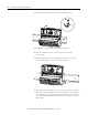
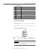
Connecting the Power Supply
Power supplied to the module must be nominally 24 Vdc (±10%) and must be
a Class 2 rated circuit.
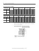
Wire the DC-input power supply to the terminal base unit as shown in Figure
2.8.
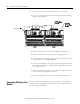
Figure 2.8 DC Input Power Supply Connections
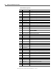
42 Relay 2 N.C. 1 Relay #2 Normally Closed contact 1
43 Relay 3 N.C. 2 Relay #3 Normally Closed contact 2
44 No Connection
45 Relay 3 N.C. 1 Relay #3 Normally Closed contact 1
46 Relay 4 N.C. 2 Relay #4 Normally Closed contact 2
47 Relay 4 N.C. 1 Relay #4 Normally Closed contact 1
48 No Connection
49 Chassis Connection to DIN rail ground spring or panel mounting hole
50 DNet V (-) DeviceNet bus power input, negative side (black wire)
51 CAN_Low DeviceNet bus connection, low differential (blue wire)
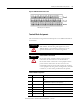
Terminal Block Assignments
No. Name Description
-
24V dc
Power
Supply
+
-
IMPORTANT
A Class 2 circuit can be provided by use of an NEC Class 2
rated power supply, or by using a SELV or PELV rated
power supply with a 5 Amp current limiting fuse installed
before the XM module(s).