XM-220 Dual Speed Module User Guide Firmware Revision 5 1440-SPD02-01RB
Important User Information Solid state equipment has operational characteristics differing from those of electromechanical equipment. Safety Guidelines for the Application, Installation and Maintenance of Solid State Controls (publication SGI-1.1 available from your local Rockwell Automation sales office or online at http://literature.rockwellautomation.com) describes some important differences between solid state equipment and hardwired electromechanical devices.
Safety Approvals The following information applies when operating this equipment in hazardous locations. Informations sur l’utilisation de cet équipement en environnements dangereux. Products marked "CL I, DIV 2, GP A, B, C, D" are suitable for use in Class I Division 2 Groups A, B, C, D, Hazardous Locations and nonhazardous locations only. Each product is supplied with markings on the rating nameplate indicating the hazardous location temperature code.
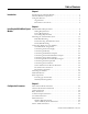
Table of Contents Chapter 1 Introduction Introducing the XM-220 Module . . . . . . . . . . . . . . . . . . . . . . . . . . . . . . 1 XM-220 Module Components. . . . . . . . . . . . . . . . . . . . . . . . . . . . . . . . . 2 Using this Manual. . . . . . . . . . . . . . . . . . . . . . . . . . . . . . . . . . . . . . . . . . . 3 Organization. . . . . . . . . . . . . . . . . . . . . . . . . . . . . . . . . . . . . . . . . . . . 3 Document Conventions . . . . . . . . . . . . . . . . . . . . . . . . . . . . .
Table of Contents vi Appendix A Specifications . . . . . . . . . . . . . . . . . . . . . . . . . . . . . . . . . . . . . . . . . . . . . . . . . . . . . . . . . 65 Appendix B DeviceNet Information Electronic Data Sheets. . . . . . . . . . . . . . . . . . . . . . . . . . . . . . . . . . . . . . 71 Changing Operation Modes. . . . . . . . . . . . . . . . . . . . . . . . . . . . . . . . . . 71 Transition to Program Mode. . . . . . . . . . . . . . . . . . . . . . . . . . . . . . 72 Transition to Run Mode .
Table of Contents vii Acknowledge Handler Object (Class ID 2BH) . . . . . . . . . . . . . . . . . . 97 Class Attributes . . . . . . . . . . . . . . . . . . . . . . . . . . . . . . . . . . . . . . . . 97 Instances. . . . . . . . . . . . . . . . . . . . . . . . . . . . . . . . . . . . . . . . . . . . . . 97 Instance Attributes. . . . . . . . . . . . . . . . . . . . . . . . . . . . . . . . . . . . . . 97 Services . . . . . . . . . . . . . . . . . . . . . . . . . . . . . . . . . . . . . . . . . . . . . . .
Table of Contents viii Publication GMSI10-UM004B-EN-P - May 2010
Chapter 1 Introduction This chapter provides an overview of the XM-220 Dual Speed module. It also discusses the components of the module.
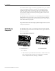
2 Introduction The module includes a single on-board relay (expandable to five), two 4-20mA outputs, and a buffered output for each input. A third buffered output is available when the module is functioning in the single redundant channel mode. This buffered output signal corresponds to the active input signal so that the machine speed can be accurately tracked regardless of which of the redundant sensors is active.
Introduction 3 • XM-220 Dual Speed Module - Mounts on the XM-941 terminal base unit via a keyswitch and a 96-pin connector. The XM-220 contains the measurement electronics, processor, relay, and serial interface port for local configuration. IMPORTANT The XM-441 Expansion Relay module may be connected to the XM-220 module via the XM-941 terminal base unit. When connected to the XM-220, the Expansion Relay module simply “expands” the capability of the XM-220 by adding four additional epoxy-sealed relays.
4 Introduction Document Conventions There are several document conventions used in this manual, including the following: The XM-220 module is referred to as XM-220, Speed module, device, or module throughout this manual. TIP EXAMPLE Publication GMSI10-UM004B-EN-P - May 2010 A tip indicates additional information which may be helpful. This convention presents an example.
Chapter 2 Installing the XM-220 Dual Speed Module This chapter discusses how to install and wire the XM-220 Dual Speed module. It also describes the module indicators and the basic operation of the module.
6 Installing the XM-220 Dual Speed Module XM Installation Requirements This section describes wire, power and grounding requirements, and instructions for an XM system. Wiring Requirements Use solid or stranded wire. All wiring should meet the following specifications: • 14 to 22 AWG copper conductors without pretreatment; 8 AWG required for grounding the DIN rail for electromagnetic interference (emi) purposes • Recommended strip length 8 millimeters (0.
Installing the XM-220 Dual Speed Module 7 Figure 2.
8 Installing the XM-220 Dual Speed Module IMPORTANT See Application Technique "XM Power Supply Solutions", publication ICM-AP005A-EN-E, for guidance in architecting power supplies for XM systems. Grounding Requirements Use these grounding requirements to ensure safe electrical operating circumstances, and to help avoid potential emi and ground noise that can cause unfavorable operating conditions for your XM system.
Installing the XM-220 Dual Speed Module 9 Figure 2.
10 Installing the XM-220 Dual Speed Module Figure 2.3 DIN Rail Grounding Block Panel/Wall Mount Grounding The XM modules can also be mounted to a conductive mounting plate that is grounded. See Figure 2.5. Use the grounding screw hole provided on the terminal base to connect the mounting plate the Chassis terminals. Figure 2.
Installing the XM-220 Dual Speed Module 11 Figure 2.5 Panel/Wall Mount Grounding 1 Power Supply 1 Power Supply 1 Use 14 AWG wire.
12 Installing the XM-220 Dual Speed Module 24V Common Grounding 24V power to the XM modules Must be grounded. When two or more power supplies power the XM system, ground the 24V Commons at a single point, such as the ground bus bar. IMPORTANT IMPORTANT If it is not possible or practical to ground the -24Vdc supply, then it is possible for the system to be installed and operate ungrounded.
Installing the XM-220 Dual Speed Module 13 Figure 2.6 Grounded DeviceNet V- at XM Module To Ground Bus ATTENTION Use of a separate DeviceNet power supply is not permitted. See Application Technique "XM Power Supply Solutions", publication ICM-AP005A-EN-E, for guidance in using XM with other DeviceNet products. For more information on the DeviceNet installation, refer to the ODVA Planning and Installation Manual - DeviceNet Cable System, which is available on the ODVA web site (http://www.odva.org).
14 Installing the XM-220 Dual Speed Module The terminal base can be DIN rail or wall/panel mounted. Refer to the specific method of mounting below. ATTENTION The XM modules make a chassis ground connection through the DIN rail. Use zinc plated, yellow chromated steel DIN rail to assure proper grounding. Using other DIN rail materials (e.g. aluminum, plastic, etc.), which can corrode, oxidize or are poor conductors can result in improper or intermittent platform grounding.
Installing the XM-220 Dual Speed Module 15 3. Rotate the terminal base onto the DIN rail with the top of the rail hooked under the lip on the rear of the terminal base. 4. Press down on the terminal base unit to lock the terminal base on the DIN rail. If the terminal base does not lock into place, use a screwdriver or similar device to open the locking tab, press down on the terminal base until flush with the DIN rail and release the locking tab to lock the base in place.
16 Installing the XM-220 Dual Speed Module 5. Gently push the side connector into the side of the neighboring terminal base unit to complete the backplane connection. Panel/Wall Mounting Installation on a wall or panel consists of: • laying out the drilling points on the wall or panel • drilling the pilot holes for the mounting screws • installing the terminal base units and securing them to the wall or panel Use the following steps to install the terminal base on a wall or panel.
Installing the XM-220 Dual Speed Module 17 1. Lay out the required points on the wall/panel as shown in the drilling dimension drawing below. Side Connector 2. Drill the necessary holes for the #6 self-tapping mounting screws. 3. Secure the terminal base unit using two #6 self-tapping screws. 4. To install another terminal base unit, retract the side connector into the base unit. Make sure it is fully retracted. 5. Position the terminal base unit up tight against the neighboring terminal base.
18 Installing the XM-220 Dual Speed Module Figure 2.7 XM-941 Terminal Base Unit XM-941, Cat. No. 1440-TB-B Terminal Block Assignments The terminal block assignments and descriptions for the XM-220 module are shown below. ATTENTION WARNING The terminal block assignments are different for different XM modules. The following table applies only to the XM-220. Refer to the installation instructions for the specific XM module for its terminal assignments.
Installing the XM-220 Dual Speed Module 19 Terminal Block Assignments No.
20 Installing the XM-220 Dual Speed Module Terminal Block Assignments No.
Installing the XM-220 Dual Speed Module 21 Figure 2.8 DC Input Power Supply Connections 24V dc Power Supply IMPORTANT IMPORTANT IMPORTANT ATTENTION + - - A Class 2 circuit can be provided by use of an NEC Class 2 rated power supply, or by using a SELV or PELV rated power supply with a 5 Amp current limiting fuse installed before the XM module(s).
22 Installing the XM-220 Dual Speed Module The alarms associated with the relay and whether the relay is normally de-energized (non-failsafe) or normally energized (failsafe) depends on the configuration of the module. Refer to Relay Parameters on page 53 for details. Table 2.1 shows the on-board relay connections for the module. IMPORTANT All XM relays are double pole. This means that each relay has two contacts in which each contact operates independently but identically.
Installing the XM-220 Dual Speed Module 23 Figures 2.9 and 2.10 illustrate the behavior of the NC and NO terminals when the relay is wired for failsafe, alarm or nonalarm condition or non-failsafe, alarm or nonalarm condition. Figure 2.9 Relay Connection - Failsafe, Nonalarm Condition Non-failsafe, Alarm Condition Figure 2.10 Relay Connection - Failsafe, Alarm Condition Non-failsafe, Nonalarm Condition Alternate Relay Wiring Figures 2.11 and 2.
24 Installing the XM-220 Dual Speed Module Figure 2.11 Relay Connection - Failsafe, Nonalarm Condition Non-failsafe, Alarm Condition Figure 2.12 Relay Connection - Failsafe, Alarm Condition Non-failsafe, Nonalarm Condition Connecting the Buffered Outputs The XM-220 provides buffered outputs of all transducer input signals. The buffered output connections may be used to connect the module to portable data collectors or other online systems. Figure 2.
Installing the XM-220 Dual Speed Module 25 Figure 2.13 Buffered Output Connections IMPORTANT The voltage operating range of the buffered outputs must be configured to coincide with the corresponding transducer bias range. This operating range is configured by placing a jumper from terminal 5 (channel 1) and terminal 22 (channel) to either terminal 6 (Positive Buffer Bias) or terminal 21 (Buffer -), depending on the transducer. See Table 2.2.
26 Installing the XM-220 Dual Speed Module The XM-220 switched buffered output can be connected to as many as 19 XM-12X modules, which includes the XM-120, XM-121, XM-122, and XM-123 modules. Figure 2.14 shows the switched buffered output connection to an XM-12X module. Figure 2.
Installing the XM-220 Dual Speed Module 27 Figure 2.15 4-20mA Output Connections - ATTENTION The 4-20mA outputs are functionally isolated from other circuits. It is recommended that the outputs be grounded at a single point. Connect the 4-20mA (-) to the XM terminal base (Chassis terminal) or directly to the DIN rail, or ground the signal at the other equipment in the 4-20mA loop.
28 Installing the XM-220 Dual Speed Module Figure 2.16 Remote Relay Reset Signal Connection ATTENTION The Switch Input circuits are functionally isolated from other circuits. It is recommended that the Switch RTN signal be grounded at a signal point. Connect the Switch RTN signal to the XM terminal base (Chassis terminal) or directly to the DIN rail, or ground the signal at the switch or other equipment that is wired to the switch.
Installing the XM-220 Dual Speed Module 29 Connecting the Startup Switch You can configure the module to detect a locked rotor condition or inhibit the tachometer fault alarm status during the start-up period. Wire the Startup switch to the terminal base unit as shown in Figure 2.18. Figure 2.18 Startup Switch Connection ATTENTION The Switch Input circuits are functionally isolated from other circuits. It is recommended that the Switch RTN signal be grounded at a signal point.
30 Installing the XM-220 Dual Speed Module Connecting a Non-Contact Sensor The figures below show the wiring of a non-contact eddy current probe to the terminal base unit. ATTENTION IMPORTANT IMPORTANT You may ground the cable shield at either end of the cable. Do not ground the shield at both ends. Recommended practice is to ground the cable shield at the terminal base and not at the transducer. Any convenient Chassis terminal may be used (see Terminal Block Assignments on page 18.
Installing the XM-220 Dual Speed Module 31 Figure 2.20 Non-contact Sensor to Channel 2 Wiring TYPICAL WIRING FOR NON-CONTACT SENSOR TO XM-220 DUAL SPEED MODULE CHANNEL 2 Isolated Sensor Driver -24 SIG COM Shield Floating Signal Common Channel 2 Input Signal Shield -24V DC 17 38 21 22 1 Jumpering terminal 21 to terminal 22 configures CH 2 buffer for -24V to 9V Connecting a Magnetic Pickup Sensor The figures below show the wiring of a passive magnetic pickup sensor to the terminal base unit.
32 Installing the XM-220 Dual Speed Module IMPORTANT An internal isolated constant current (0.5mA) supply is provided to detect a cable or transducer fault (short). This current is enabled with the Enable Bias Current parameter. Refer to Channel Tachometer Parameters on page 47. Figure 2.
Installing the XM-220 Dual Speed Module 33 Figure 2.22 Magnetic Pickup to Channel 2 Wiring T Y P IC A L W IR IN G F O R M A G N E T IC P IC K U P S E N S O R TO XM -220 D U AL SPEED M O DU LE C H AN N EL 1 Cable shield not connected at this end Signal Common Channel 2 Input Signal Shield 17 1 38 Connecting a TTL Output Device The figures below show the wiring of a TTL output device to the terminal base unit. ATTENTION IMPORTANT You may ground the cable shield at either end of the cable.
34 Installing the XM-220 Dual Speed Module Figure 2.23 TTL Output Device to Channel 1 Wiring TYPICAL WIRING FOR TTL OUTPUT DEVICE TO XM-220 DUAL SPEED MODULE CHANNEL 1 Cable shield not connected at this end Signal Common Channel 1 Input Signal 16 Shield 0 38 +24V DC 6 Figure 2.
Installing the XM-220 Dual Speed Module 35 Sensor Placement for Reverse Rotation The XM-220 module uses two input signals for reverse rotation detection. Connect the first sensor to Channel 1. Connect the second sensor to Channel 2. Refer to Connecting a Non-Contact Sensor on page 30 for wiring details. Position the sensors so that: • The keyway passes Channel 1 sensor before it passes Channel 2 sensor as the machine rotates in the forward direction, as illustrated in Figure 2.25. Figure 2.
36 Installing the XM-220 Dual Speed Module Figure 2.26 Spacing of the Sensors CH 1 SENSOR CH 1 SENSOR CH 1 SENSOR CH 2 SENSOR CH 2 SENSOR CH 2 SENSOR YES CH 1 SENSOR CH 1 SENSOR CH 1 SENSOR CH 2 SENSOR CH 2 SENSOR NO CH 2 SENSOR IMPORTANT Make certain to set the Measurement Mode parameter to "Reverse Rotation." Refer to Measurement Mode Parameter on page 46.
Installing the XM-220 Dual Speed Module 37 • Mini-Connector - The mini-connector is located on the top of the module, as shown below. Figure 2.27 Mini-Connector 1440-SPD02-01RB DUAL SPEED mini-connector A special cable (Cat. No. 1440-SCDB9FXM2) is required for this connection. The connector that inserts into the PC is a DB-9 female connector, and the connector that inserts into the module is a USB Mini-B male connector.
38 Installing the XM-220 Dual Speed Module Connect the DeviceNet cable to the terminal base unit as shown. Connect To Terminal Red Wire DNet V+ 26 (Optional - see note) White Wire CAN High 23 Bare Wire Shield (Chassis) 10 Blue Wire CAN Low 24 Black Wire DNet V- 27 IMPORTANT The DeviceNet power circuit through the XM module interconnect, which is rated at only 300 mA, is not intended or designed to power DeviceNet loads. Doing so could damage the module or terminal base.
Installing the XM-220 Dual Speed Module 39 use the XM Serial Configuration Utility or RSNetWorx™ for DeviceNet™ (Version 3.0 or later) to set the network node address. Refer to the appropriate documentation for details. IMPORTANT Mounting the Module The baud rate for the XM-220 is set by way of "baud detection" (Autobaud) at power-up. The XM-220 mounts on the XM-941 terminal base unit, Cat. No. 1440-TB-B.
40 Installing the XM-220 Dual Speed Module 1. Make certain the keyswitch (A) on the terminal base unit (C) is at position 4 as required for the module. 2. Make certain the side connector (B) is pushed all the way to the left. You cannot install the module unless the connector is fully extended. 3. Make sure that the pins on the bottom of the module are straight so they will align properly with the connector in the terminal base unit. 4.
Installing the XM-220 Dual Speed Module 41 Figure 2.28 LED Indicators 1440-SPD02-01RB DUAL SPEED Module Indicators The following tables describe the states of the LED status indicators. Module Status (MS) Indicator Color State Description No color Off No power applied to the module. Green Flashing Red Module performing power-up self test. Flashing Module operating in Program Mode1. Solid Module operating in Run Mode2. Flashing • Application firmware is invalid or not loaded.
42 Installing the XM-220 Dual Speed Module Network Status (NS) Indicator Color State Description No color Off Module is not online. • Module is autobauding. • No power applied to the module, look at Module Status LED. Green Red 1 Flashing Module is online (DeviceNet) but no connections are currently established.1 Solid Module is online with connections currently established. Flashing One or more I/O connections are in the timed-out state.
Installing the XM-220 Dual Speed Module 43 Relay Indicator Basic Operations Color State Description Red Off On-board relay is not activated. Solid On-board relay is activated. Powering Up the Module The XM-220 performs a self-test at power-up. The self-test includes an LED test and a device test. During the LED test, the indicators will be turned on independently and in sequence for approximately 0.25 seconds. The device test occurs after the LED test.
44 Installing the XM-220 Dual Speed Module Figure 2.29 Reset Switch 1440-SPD02-01RB DUAL SPEED Press the Reset Switch to reset the relays The switch can be used to reset all latched relays in the module. This includes the relays in the Expansion Relay Module when it is attached to the XM-220. IMPORTANT Publication GMSI10-UM004B-EN-P - May 2010 The Reset switch resets the relays only if the input is no longer in alarm or the condition that caused the alarm is no longer present.
Chapter 3 Configuration Parameters This chapter provides a complete listing and description of the XM-220 parameters. The parameters can be viewed and edited using the XM Serial Configuration Utility software and a personal computer. If the module is installed on a DeviceNet network, configuring can also be performed using a network configuration tool such as RSNetWorx (Version 3.0 or later). Refer to your configuration tool documentation for instructions on configuring a device.
46 Configuration Parameters Measurement Mode Parameter The Measurement Mode parameter controls how the two sensors are used to calculate the speed, acceleration, and peak measurements. The XM-220 module operates in three different modes: • Dual Channel - This is the default mode. The two sensors are used independently to perform two separate sets of speed, acceleration, and peak speed measurements.
Configuration Parameters Channel Tachometer Parameters 47 The Tachometer parameters define the characteristics of the tachometer and determine the signal processing that will be performed on the tachometer signal. There are two instances of the tachometer parameters, one for each channel. TIP IMPORTANT IMPORTANT IMPORTANT The Channel LED will flash red when a transducer fault condition exists on the channel even if you are not using the channel.
48 Configuration Parameters Tachometer Parameters Parameter Name Description XM Configuration EDS File Utility Controls whether a small amount of current is injected into the sensor wiring to help detect transducer faults of passive magnetic sensors. Enable Bias Current Bias Current Passive magnetic sensors are unbiased and provide no inherent fault detection capability.
Configuration Parameters 49 Tachometer Parameters Parameter Name Description DC Bias Time Constant The time constant used for exponential averaging Seconds (low pass filtering) of the transducer DC bias measurement. The corner frequency for the low pass filter is 1 / (2 x π x DC Bias Time Constant). See example table below. XM Configuration EDS File Utility Auto Trigger Trigger Hysteresis Trigger Mode Values/Comments Time Constant (seconds) -3dB Frequency (Hz) Settling (seconds) 1 0.159 2.
50 Configuration Parameters Tachometer Parameters Parameter Name Description Values/Comments Trigger Threshold The signal level to be used as the trigger value when in Manual Trigger mode. Enter a value from +16 to -16 volts dc. Note: This value is not used in Auto Trigger mode. Trigger Slope The input signal slope to be used as the trigger value. Options: Positive Negative Pulses per Revolution The number of tachometer signal pulses per revolution of the shaft (number of gear teeth).
Configuration Parameters 51 Alarm Parameters Parameter Name Description Values/Comments Name (XM Serial Configuration Utility only) A descriptive name to identify the alarm in the XM Serial Configuration Utility. Maximum 18 characters Note: This parameter is not applicable for Locked Rotor alarms. Enable Enable/disable the selected alarm. Note: The Alarm Status is set to "Disarm" when the alarm is disabled. Condition Controls when the alarm should trigger.
52 Configuration Parameters Alarm Parameters Parameter Name Description Values/Comments Alert Threshold (High) The threshold value for the alert (alarm) condition. The thresholds shall be specified in the units of the associated measurement (for example, RPM for speed, RPM/min for acceleration). Important: For Locked Rotor alarms, the Alert Threshold value must be less than or equal to the Danger Threshold value.
Configuration Parameters 53 Alarm Parameters Parameter Name Description Values/Comments Startup Period The length of time that the tachometer fault is inhibited after the startup period. The startup period begins when the startup switch is reopened (push button disengaged or toggle switch flipped to off). Enter a value from 0 to 1092 minutes, adjustable in increments of 0.1 minutes. Note: This parameter is not applicable for Locked Rotor alarms.
54 Configuration Parameters Relay Parameters Parameter Name Description Options/Comments Number (XM Serial Configuration Utility only) Sets the relay to be configured in the XM Serial Configuration Utility. Relay Number 1 is the on-board relay. Numbers 2 through 5 are either relays on the Expansion Relay module when it’s connected to the module or virtual relays. Virtual relays are non-physical relays.
Configuration Parameters 55 Relay Parameters Parameter Name Description XM Configuration EDS File Utility Activation Logic Logic XM Configuration EDS File Utility Alarm A/B Alarm Identifier A/B Options/Comments Options: A only A or B A and B • A or B - Relay is activated when either Alarm A or Alarm B meets or exceeds the selected Alarm Status condition(s). • A and B - Relay is activated when both Alarm A and Alarm B meet or exceed the selected Alarm Status condition(s).
56 Configuration Parameters Relay Parameters Parameter Name XM Configuration EDS File Utility Alarm Status to Activate On Description Options/Comments Sets the alarm conditions that will cause the relay to activate. You can select more than one. Options: Normal Danger Xdcr Fault Tacho Fault Alert Disarm Module Fault Alarm Levels • Normal - The current measurement is not within excess of any alarm thresholds.
Configuration Parameters 57 Relay Parameters Parameter Name Description XM Configuration EDS File Utility Failsafe Relay Failsafe Option Determines whether the relay is failsafe or non-failsafe. Failsafe operation means that when in alarm, the relay contacts are in their "normal," de-energized, or "shelf-state" positions. In other words, normally closed relays are closed in alarm, and normally open relays are open in alarm. With failsafe operation, a power failure equals an alarm.
58 Configuration Parameters 4-20mA Output Parameters The 4-20mA output parameters define the characteristics of the two 4-20mA output signals. The parameters are the same for each output. 4-20mA Parameters Parameter Name Description Options/Comments Enable Enables/disables the 4-20mA output. XM Configuration Utility EDS File Check to enable Enabled Clear to disable Disabled Measurement Sets the type of measurement and the channel that the 4-20mA output signal will track.
Configuration Parameters I/O Data Parameters 59 The I/O data parameters are used to configure the content and size of the DeviceNet I/O Poll response message. IMPORTANT The XM-220 must be free of Poll connections when configuring the Poll Output (Poll Response Assembly) and Poll Size. Any attempt to download the parameters while a master has established the Poll connection with the XM-220 will result in error.
60 Configuration Parameters The Data parameters are used to view the measured values of the input channels, as well as to monitor the status of the channels, alarms, and relays. Data Parameters TIP To view all the data parameters in the XM Serial Configuration Utility, click the View Data tab. Monitor Data Parameters Monitor Data Parameters Parameter Name Description Values/Comments Speed Shows the measured speed value. Acceleration Shows the measured acceleration value.
Configuration Parameters 61 Alarm and Relay Status Parameters Alarm and Relay Status Parameters Parameter Name Description Values/Comments Speed Alarm Status States the current status of the speed alarm. Possible status values: Acceleration Alarm Status States the current status of the acceleration alarm Zero Speed Alarm Status States the current status of the zero speed alarm.
62 Configuration Parameters Alarm and Relay Status Parameters Parameter Name Description Values/Comments Locked Rotor Alarm Status States the current status of the locked rotor alarm. Possible status values: • Normal - The alarm is enabled, the device is in Run mode, there is no transducer fault, and the current measurement is not within the Alert or Danger Threshold value(s).
Configuration Parameters Device Mode Parameters 63 The Device Mode parameters are used to control the functions and the behavior of the device. IMPORTANT The XM Serial Configuration Utility handles these parameters automatically and transparently to the user. Device Mode Parameters Parameter Name Description Values/Comments Device Mode Sets the current operation mode of the device. Refer to Changing Operation Modes on page 71 for more information.
64 Configuration Parameters Publication GMSI10-UM004B-EN-P - May 2010
Appendix A Specifications The Appendix lists the technical specifications for the XM-220 module. XM-220 Technical Specifications Product Feature Specification Communications DeviceNet Standard DeviceNet protocol for all functions NOTE: The XM-220 uses only the DeviceNet protocol, not power. Module power is provided independently.
66 Specifications XM-220 Technical Specifications Product Feature Specification Inputs 2 Tachometer Inputs ±25V (50V maximum peak to peak) Eddy current transducer signals Magnetic pickups TTL output devices Input Impedance 120k ohms minimum Speed/Frequency Range 1 to 1,200,000 RPM 0.0167 to 20,000 Hz Speed Measurement Error 1 to 240 RPM 241 to 12,000 RPM 12,001 to 20,400 RPM 20,401 to 120,000 RPM 120,001 to 360,000 RPM 360,001 to 1,200,000 RPM ±0.
Specifications 67 XM-220 Technical Specifications Product Feature Specification Measured Parameters Direction Forward Reverse Speed Acceleration Peak Speed Gap (or transducer bias voltage) Measured Units RPM Direction of Rotation Acceleration in RPM / Minute Measurement Modes Dual Channel Two sensors are used independently to perform two separate speed, acceleration and peak speed measurements. Single Redundant Channel One sensor is used to perform the speed, acceleration and peak speed measurements.
68 Specifications XM-220 Technical Specifications Product Feature Specification Relays Number Single on-board relay, two sets of contacts DPDT (2 Form C) Four additional relays when interconnected to an XM-441 Expansion Relay module, or Four virtual relays whose status can be used by remote Control Systems or the XM-440 Master Relay module On-board Relay Rating Maximum Voltage: 120V dc, 125V ac Maximum Current: 3.5A* Minimum Current: 0 Maximum Power: 60W, 62.
Specifications 69 XM-220 Technical Specifications Product Feature Specification Non-Volatile Configuration A copy of the module configuration is retained in non-volatile memory from where it is loaded upon power up*. *The configuration stored in non-volatile memory can be deleted only by a command sent via the serial interface, using the Serial Configuration Utility, or via DeviceNet from any compliant software application. Power Module +21.6 to +26.
70 Specifications XM-220 Technical Specifications Product Feature Approvals (when product or packaging is marked) Specification UL UL Listed for Ordinary Locations UL UL Listed for Class I, Division 2 Group A, B, C, and D Hazardous Locations CSA CSA Certified Process Control Equipment CSA CSA Certified Process Control Equipment for Class I, Division 2 Group A, B, C, and D Hazardous Locations EEX* European Union 94/9/EEC ATEX Directive, compliant with EN 50021; Potentially Explosive Atmospheres,
Appendix B DeviceNet Information Electronic Data Sheets Electronic Data Sheet (EDS) files are simple text files used by network configuration tools such as RSNetWorx (Version 3.0 or later) to help you identify products and easily commission them on a network. The EDS files describe a product’s device type, product revision, and configurable parameters on a DeviceNet network. The EDS files for the XM modules are installed on your computer with the XM configuration software.
72 DeviceNet Information Transition to Program Mode Parameter values can only be downloaded to an XM module while the module is in Program mode. Any attempt to download a parameter value while the module is in Run mode will result in a Device State Conflict error. To transition the XM module from Run mode to Program mode on a DeviceNet network, set the Device Mode parameter to "Program mode" and click Apply.
DeviceNet Information 73 The table below defines services supported by the XM modules. The table includes the service codes, classes, instances, and attributes by their appropriate hexadecimal codes. Use the Class Instance Editor in RSNetWorx to execute these services, as illustrated in the example below.
74 DeviceNet Information Example To save the configuration parameters to the non-volatile memory (EEPROM), fill in the Class Instance Editor as shown below. Clear Send the attribute ID and then enter the Class (320 hex) and Instance (1) Select the Save service code Click Execute to initiate the action Invalid Configuration Errors A Start or Save service request to an XM module may return an Invalid Device Configuration error when there is a conflict amongst the configuration settings.
DeviceNet Information 75 Additional Error Codes returned with the Invalid Device Configuration Error (0xD0) XM-220 I/O Message Formats Error Code (Hex) Description 0A Too many alarms associated with a single measurement. 0B Invalid node address in the alarm list. 0C Too many alarms in the alarm list. Or, no alarms in the alarm list. 0D Alarm levels cannot be zero for alarms that are enabled. 0E Too many slaves in the scanner’s input data table.
76 DeviceNet Information The following tables show the static data formats of Assembly instances 101– 103.
DeviceNet Information 77 COS Message Format The XM-220 COS message contains five bytes of data as defined in the table below. The COS data can also be requested explicitly through Assembly Object (Class ID 0x4), Instance 100 (0x64), Data Attribute (3).
78 DeviceNet Information Relay Status Descriptions Relay Status Value Description 0 Not Activated 1 Activated Reverse Rotation Status Descriptions ADR for XM Modules Reverse Rotation Status Value Descriptions 0 Forward 1 Reverse Automatic Device Replacement (ADR) is a feature of an Allen-Bradley DeviceNet scanner. It provides a means for replacing a failed device with a new unit, and having the device configuration data set automatically.
DeviceNet Information 79 • The ADR scanner can not download the configuration data to an XM module if the module has a saved configuration in its non-volatile memory. This happens because the saved configuration is restored and the module enters Run mode when the power is cycled. (Configuration parameters cannot be downloaded while an XM module is in Run mode.) XM modules must be in Program mode for the ADR configuration to be downloaded and this occurs only when there is no saved configuration.
80 DeviceNet Information – All SU/CD Trend related parameters – Custom Assembly structure (see page 59) • The ADR and trigger group functions cannot be used together. A module can have only one primary master so a module cannot be both configured for ADR and included in a trigger group. The ADR scanner must be the primary master for the modules configured for ADR. The XM-440 Master Relay module must be the primary master for modules included in a trigger group.
Appendix C DeviceNet Objects Appendix C provides information on the DeviceNet objects supported by the XM-220 module.
82 DeviceNet Objects The Identity Object provides identification and general information about the device. Identity Object (Class ID 01H) Class Attributes The Identity Object provides no class attributes. Instance Attributes Table C.
DeviceNet Objects 83 Table C.2 Identity Object Status Bit Name Description 4 Boot Program Vendor-specific, indicates that the boot program is running. The Main Application must be corrupt or missing. 5-7 Vendor-specific, not implemented 8 Minor Recoverable Fault Set whenever there is a transducer or tachometer fault. 9 Minor Unrecoverable Fault Not implemented 10 Major Recoverable Fault Set when the module detects a major problem that the user may be able to recover from.
84 DeviceNet Objects The DeviceNet Object is used to provide the configuration and status of a physical attachment to DeviceNet. DeviceNet Object (Class ID 03H) Class Attributes Table C.4 DeviceNet Object Class Attributes Attr ID Access Rule Name Data Type Default Value 1 Get Revision UINT 2 Instance Attributes Table C.
DeviceNet Objects 85 rate detection instead. This means that the module will determine the network baud rate by listening for network traffic before attempting to go online. Services Table C.
86 DeviceNet Objects Table C.8 Assembly Object Instances Instance Name Type Description 101 Default Poll Response Message Input Measurement values 102 - 106 Alternate Poll Response Message Input Measurement values 199 Alternate Dynamic Poll Response Message Input User configurable measurement values and configuration parameters Instance Attributes Table C.
DeviceNet Objects 87 Table C.10 Instance 100 Data Format (Alarm and Relay Status Values Assembly) Byte Bit 7 Bit 6 Bit 5 Bit 4 Bit 3 Bit 2 Bit 1 Bit 0 2 Relay 3 Status 0 Alarm 6 Status (CH2 Zero Speed Alarm) Alarm 5 Status (CH1 Zero Speed Alarm) 3 Relay 4 Status 0 Locked Rotor Alarm 2 Status Locked Rotor Alarm 1 Status 4 Relay 5 Status 0 0 0 Instance 101 - Measurement Values This assembly can be selected to be sent in response to an I/O Poll request from a master.
88 DeviceNet Objects Instance 103 - Measurement Values This assembly can be selected to be sent in response to an I/O Poll request from a Master. This assembly includes all the Channel 1 measurements first. Table C.
DeviceNet Objects 89 Table C.
90 DeviceNet Objects Class Attributes The Connection Object provides no class attributes. Instances Table C.16 Assembly Object Instances Instance Description 1 Explicit Message Connection for pre-defined connection set 2 I/O Poll Connection 4 I/O COS (change of state) Connection 11 - 17 Explicit Message Connection Instance Attributes Table C.17 Connection Object Instance Attributes Attr ID Access Rule Name Data Type Description 1 Get State USINT State of the object.
DeviceNet Objects 91 Table C.17 Connection Object Instance Attributes Attr ID Access Rule 14 Name Data Type Description Get Produced Connection Path Array of USINT Specifies the Application Object(s) whose data is to be produced by this Connection Object. See DeviceNet Specification Volume 1 Appendix I. 15 Get Consumed Connection Path Length UINT Number of bytes in the consumed_connection_path attribute.
92 DeviceNet Objects Instance Attributes Table C.20 Discrete Input Object Instance Attributes Attr ID Access Rule Name Data Type Description Semantics 3 Get Value BOOL Value 0 = Off 1 = On 199 Set Backdoor Service USINT Setting this attribute is equivalent to requesting the specified service. Set to one of the following values to perform the specified service: 0x32 = Open 0x33 = Close For instance 1, a Value of 1 means that the startup period is active.
DeviceNet Objects 93 Class Attributes Table C.22 Parameter Object Class Attributes Attr ID Access Rule Name Data Type Description Semantics 2 Get Max Instance UINT Maximum instance number of an object in this class. Total number of parameter object instances. 8 Get Parameter Class WORD Descriptor Bits that describe the parameter. Bit 0 Supports Parameter Instances Bit 1 Supports Full Attrib. Bit 2 Must do non-volatile store Bit 3 Params in non-volatile 9 Get Config.
94 DeviceNet Objects Table C.
DeviceNet Objects 95 Table C.
96 DeviceNet Objects Instance Attributes Table C.24 Parameter Object Instance Attributes Attr ID Access Rule 1 Set Parameter Value 2 Get Link Path Size USINT Size of Link Path 3 Get Link Path ARRAY of DeviceNet path DeviceNet path to the object for the Parameter value. Segment Type/Port BYTE See DeviceNet Specification Volume 1 Appendix I for format. Name Data Type Description Semantics Actual value of parameter See Table C.23 for a list of valid values for each instance.
DeviceNet Objects 97 The Acknowledge Handler Object is used to manage the reception of message acknowledgments. This object communicates with a message producing Application Object within a device. The Acknowledge Handler Object notifies the producing application of acknowledge reception, acknowledge timeouts, and production retry limit errors. Acknowledge Handler Object (Class ID 2BH) Class Attributes The Acknowledge Handler Object provides no class attributes.
98 DeviceNet Objects The Alarm Object models a two-stage (alert and danger levels) alarm. Alarm Object (Class ID 31DH) Class Attributes The Alarm Object provides no class attributes. Instances There are 6 instances of this object. Table C.28 Alarm Object Instances Instance Measurement Alarm 1 Channel 1 Speed Alarm 2 Channel 2 Speed Alarm 3 Channel 1 Acceleration Alarm 4 Channel 2 Acceleration Alarm 5 Channel 1 Zero Speed Alarm 6 Channel 2 Zero Speed Instance Attributes Table C.
DeviceNet Objects 99 Table C.29 Alarm Object Instance Attributes Attr ID Access Rule 8 Name Data Type Description Semantics Get/Set Alert Threshold (High) REAL The threshold value for the alert (alarm) condition (greater threshold for range types). 9 Get/Set Danger REAL Threshold (High) The threshold value for the danger (shutdown) condition (greater threshold for range types).
100 DeviceNet Objects The Device Mode Object is used to control access to the configuration parameters in the module. This object’s Device Mode attribute must be in PROGRAM mode to allow the module’s configuration parameters to be "Set" (see Services). Attempts to set the configuration parameters while the Device Mode is in RUN mode will return an error. Note that the module collects measurements while in RUN mode but not while it is in PROGRAM mode.
DeviceNet Objects 101 Table C.32 Device Mode Object Services Service Code Class/Instance Usage Name Description 06h Instance Start Validate the device configuration settings and transition to the Run state if OK. 05h Instance Reset Transition to the Power Up state. Load the non-volatile configuration and transition to the Run state if saved configuration restored. 16h Instance Save Validate the device configuration settings if necessary and save them to non-volatile memory.
102 DeviceNet Objects Instances There are 5 instances of this object. Instance Attributes Table C.34 Relay Object Instance Attributes Attr ID Access Rule Name Data Type Description Semantics 3 Get Relay Status BOOL The current status of the relay. 0 = Off 1 = On 4 Get/Set Relay Enable BOOL Indicates whether this relay object is enabled. 0 = Disabled 1 = Enabled 5 Get/Set Latch Enable BOOL Indicates whether this relay latches (requires a reset command to deactivate).
DeviceNet Objects 103 Table C.34 Relay Object Instance Attributes Attr ID Access Rule 11 Name Data Type Description Semantics Get/Set Alarm Identifier B EPATH Identifies the second alarm status the relay monitors. See Parameter Object instances 9 to 13. 12 Get/Set Logic USINT Indicates the number of associated alarms that must have a status value specified by Alarm Level in order to activate the relay.
104 DeviceNet Objects Speed Measurement Object (Class ID 325H) The Speed Measurement Object models a speed measurement of a tachometer signal. Class Attributes The Speed Measurement Object provides no class attributes. Instances There are 2 instances of the object. Instance Attributes Table C.36 Speed Measurement Object Instance Attributes Attr ID Access Rule Name Data Type Description Semantics 3 Get Speed Value REAL The measured speed value.
DeviceNet Objects 105 Table C.36 Speed Measurement Object Instance Attributes Attr ID Access Rule 8 Name Data Type Description Semantics Get/Set Locked Rotor Alert Threshold REAL The minimum machine speed that must be obtained within the alert period to avoid an alert status. CPM 9 Get/Set Locked Rotor Danger Threshold REAL The minimum machine speed that must be obtained within the danger period to avoid a danger status.
106 DeviceNet Objects Tachometer Channel Object (Class ID 326H) The Tachometer Channel Object models "front end" processing performed on a tachometer signal before specific measurements are performed. Class Attributes The Tachometer Channel Object provides no class attributes. Instances There are 2 instances of this object. Instance Attributes Table C.
DeviceNet Objects 107 Table C.38 Tachometer Channel Object Instance Attributes Attr ID Access Rule Name Data Type Description Semantics 8 Get/Set Name STRING2 A name to help identify this channel 18 character maximum 9 Get/Set Multiplier REAL A multiplier applied to the > 0 tachometer pulse rate. 10 Get/Set Fault Time-out USINT Number of seconds with no pulses before a Tach Fault is indicated. 1 to 64 seconds Services Table C.
108 DeviceNet Objects Instance Attributes Table C.40 Transducer Object Instance Attributes Attr ID Access Rule Name Data Type Description 3 Get DC Bias REAL The measured average DC Volts bias of the transducer signal in volts. 4 Get Status BOOL 0 = No fault Indicates whether a 1 = A transducer fault exists transducer fault exists (the measured DC Bias is outside the range specified by Fault High and Low).
DeviceNet Objects 4-20mA Output Object (Class ID 32AH) 109 The 4-20mA Output Object models the configuration of a 4-20mA output signal. Class Attributes The 4-20mA Output Object provides no class attributes. Instances There are 2 instances of this object. Instance Attributes Table C.42 4-20mA Output Object Instance Attributes Attr ID Access Rule Name Data Type Description Semantics 3 Get Value REAL The current output value.
110 DeviceNet Objects Services Table C.43 4-20mA Output Object Services Service Code Class/Instance Usage Name Description 0Eh Instance Get_Attribute_Single Returns a single attribute. 10h Instance Set_Attribute_Single Sets a single attribute.1 1 Publication GMSI10-UM004B-EN-P - May 2010 Attributes can only be set while the device is in Program Mode. See the description of the Device Mode Object for more information.
Glossary alarm An alarm alerts you to a change in a measurement. For example, an alarm can notify you when the measured vibration level for a machine exceeds a pre-defined value. Automatic Device Replacement (ADR) A means for replacing a malfunctioning device with a new unit, and having the device configuration data set automatically. The ADR scanner uploads and stores a device’s configuration.
Glossary 112 current configuration The current configuration is the most recently loaded set of configuration parameters in the XM module’s memory. When power is cycled, the current configuration is loaded with either the saved configuration (in EEPROM) or the factory defaults (if there is no saved configuration). In addition, the current configuration contains any configuration changes that have been downloaded to the module since power is applied.
Glossary 113 Help window A window that contains help topics that describe the operation of a program. These topics may include: • • • • An explanation of a command. A description of the controls in a dialog box or property page. Instructions for a task. Definition of a term. MAC ID See node address. master device A device which controls one or more slave devices. The XM-440 Master Relay module is a master device. node address A DeviceNet network can have as many as 64 devices connected to it.
Glossary 114 Program mode The XM module is idle. Typically this occurs when the module configuration settings are being updated with the XM Configuration program. In Program mode, the signal processing/measurement process is stopped. The status of the alarms is set to the disarm state to prevent a false alert or danger status. Run mode In Run mode, the module collects measurement data and monitors each measurement device.
Index Numerics 24V common grounding requirements 12 4-20mA Output Object 109 4-20mA output parameters 58 Enable 58 Max Range 58 Measurement 58 Min Range 58 4-20mA outputs, wiring 26 A Acknowledge Handler Object 97 Alarm Object 98 alarm parameters 50 Alarm 50 Alert Period 52 Alert Threshold (High) 52 Alert Threshold (Low) 52 Condition 51 Danger Period 52 Danger Threshold (High) 52 Danger Threshold (Low) 52 Enable 51 Hysteresis 52 Inhibit Tachometer Fault 53 Name 51 Startup Period 53 Assembly Object 85 B b
116 Index I/O message formats 75 invalid device configuration errors 74 setting the Device Mode parameter 71, 72 XM services 73 DeviceNet Object 84 DeviceNet objects 81 4-20mA Output 109 Acknowledge Handler 97 Alarm 98 Assembly 85 Connection 89 Device Mode 100 DeviceNet 84 Discrete Input Point 91 Identity 82 Parameter 92 Relay 101 Speed Measurement 104 Tachometer Channel 106 Transducer 107 DIN Rail Grounding Block 9 DIN rail grounding requirements 8 Discrete Input Point Object 91 document conventions 4 du
Index P panel/wall mount grounding requirements 10 Parameter Object 92 poll message format 75 Assembly instance 101 76 Assembly instance 102 76 Assembly instance 103 76 power requirements 6 power supply, wiring 20 program mode 41, 71 R relay contacts normally closed 21 normally open 21 Relay indicator 43 Relay Object 101 relay parameters 53 Activation Delay 54 Activation Logic 55 Alarm A 55 Alarm B 55 Alarm Identifier A 55 Alarm Identifier B 55 Alarm Levels 56 Alarm Status to Activate On (Alarm Levels) 56
118 Index serial port 36 startup switch 29 switched buffered output 25 transducers 29 wiring requirements 6 X XM Services 73 XM status values 77 XM-220 Dual Speed Module components 2 configuration parameters 45 description 3 grounding requirements 8 Publication GMSI10-UM004B-EN-P - May 2010 indicators 40 introduction 1 mounting 39 power requirement 6 reset switch 43 self-test 43 specifications 65 wiring requirements 6 XM-220 I/O message formats 75 XM-441 Expansion Relay Module 3, 53 XM-941 terminal bas
Rockwell Automation Support Rockwell Automation provides technical information on the Web to assist you in using its products. At http://support.rockwellautomation.com, you can find technical manuals, a knowledge base of FAQs, technical and application notes, sample code and links to software service packs, and a MySupport feature that you can customize to make the best use of these tools.