
Owner manual

Publication GMSI10-UM004B-EN-P - May 2010
20 Installing the XM-220 Dual Speed Module
1 Terminals are internally connected and isolated from the Chassis terminals.
2 When the XM-220 is used as part of an Electronic Overspeed Detection System, redundant power may be
applied directly to the module per the XM Electronic Overspeed Detection System User Guide, publication
GMSI10-UM015A-EN-E.
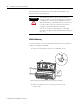
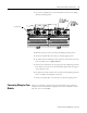
Connecting the Power Supply
Power supplied to the module must be nominally 24 Vdc (±10%) and must be
a Class 2 rated circuit.
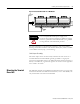
Wire the DC-input power supply to the terminal base unit as shown in Figure
2.8.
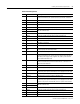
35 Chassis Connection to DIN rail ground spring or panel mounting hole
36 Chassis Connection to DIN rail ground spring or panel mounting hole
37 Chassis Connection to DIN rail ground spring or panel mounting hole
38 Chassis Connection to DIN rail ground spring or panel mounting hole
39 Start Switch input to activate startup switch (active closed)
40 Switch RTN Switch return for Start and Reset Relay
41 Reset Relay Switch input to reset internal relay (active closed)
42 +24V In 2 (EODS
ONLY)
Connection to an external +24V power supply, positive side, when used as
a part of an EODS system
2
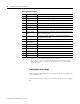
43
24V Common
1
Connection to external +24V power supply, negative side (internally
DC-coupled to circuit ground)
44 +24V In Connection to primary external +24V power supply, positive side
45
24V Common
1
Internally DC-coupled to circuit ground
46 Relay N.C. 1 Relay Normally Closed contact 1
47 Relay Common 1 Relay Common contact 1
48 Relay N.O. 1 Relay Normally Open contact 1
49 Relay N.O. 2 Relay Normally Open contact 2
50 Relay Common 2 Relay Common contact 2
51 Relay N.C. 2 Relay Normally Closed contact 2
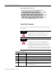
Terminal Block Assignments
No. Name Description