
Manual


Publication GMSI10-UM013D-EN-P - May 2010
172 DeviceNet Objects
Instance Attributes
Services
1 Attributes can only be set while the device is in Program Mode. See the description of the Device Mode Object
for more information.
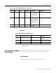
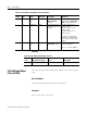
Table C.60 Tachometer Channel Object Instance Attributes
Attr ID
Access
Rule Name Data Type Description Semantics
3 Get/Set Number of
Pulses per
Revolution
UINT The number of signal
pulses per revolution of
the shaft (number of gear
teeth).
0 = Tachometer disabled
> 0 = Tachometer enabled
4 Get/Set Auto Trigger BOOL Indicates whether the
trigger level is determined
automatically from the
signal.
0 = Use specified Trigger Level
and Hysteresis
1 = Determine trigger level and
hysteresis automatically
5 Get/Set Trigger Level REAL The signal level to be
used as the trigger.
Volts
6 Get/Set Trigger Slope USINT The slope of the signal at
the threshold crossing to
be used as the trigger.
0 = Positive
1 = Negative
7 Get/Set Trigger
Hysteresis
REAL The amount of hysteresis
around the trigger level.
In Auto Trigger mode, this
value is a percentage of the
peak-to-peak input signal and
can range from 0 to 50%. In
Manual Trigger mode, this
value is a voltage level (the
hysteresis voltage is added or
subtracted to the threshold
voltage to determine the
hysteresis range).
8 Get/Set Name STRING2 A name to help identify
this channel.
18 characters maximum
10 Get/Set Fault Time-out USINT Number of seconds with
no pulses before a Tach
Fault is indicated.
1 to 64 seconds
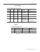
Table C.61 Tachometer Channel Object Services
Service
Code Class/Instance Usage Name Description
0E
h
Instance Get_Attribute_Single Returns a single attribute.
10
h
Instance Set_Attribute_Single
Sets a single attribute.
1