
Manual

Publication GMSI10-UM013D-EN-P - May 2010
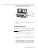
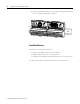
20 Installing the XM-122 gSE Vibration Module
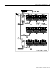
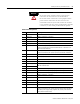
1 Terminals are internally connected and isolated from the Chassis terminals.
22 Buffer Power 2 IN Channel 2 buffer power input
Connect to terminal 6 for positive biased transducers or terminal 21 for
negative biased transducers
23 CAN_High DeviceNet bus connection, high differential (white wire)
24 CAN_Low DeviceNet bus connection, low differential (blue wire)
25 +24V Out Internally connected to 24V In 1 (terminal 44)
Used to daisy chain power if XM modules are not plugged into each other
26 DNet V (+) DeviceNet bus power input, positive side (red wire)
27 DNet V (-) DeviceNet bus power input, negative side (black wire)
28
24 V Common
1
Internally connected to 24 V Common (terminals 43 and 45)
Used to daisy chain power if XM modules are not plugged into each other
If power is not present on terminal 44, there is no power on this terminal
29 4-20 mA 2 (+) 4-20 mA output
300 ohm maximum load
30 4-20 mA 2 (-)
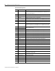
31 Chassis Connection to DIN rail ground spring or panel mounting hole
32 Chassis Connection to DIN rail ground spring or panel mounting hole
33 Chassis Connection to DIN rail ground spring or panel mounting hole
34 Chassis Connection to DIN rail ground spring or panel mounting hole
35 Chassis Connection to DIN rail ground spring or panel mounting hole
36 Chassis Connection to DIN rail ground spring or panel mounting hole
37 Chassis Connection to DIN rail ground spring or panel mounting hole
38 Chassis Connection to DIN rail ground spring or panel mounting hole
39 SetPtMult Switch input to activate Set Point Multiplication (active closed)
40 Switch RTN Switch return, shared between SetPtMult and Reset Relay
41 Reset Relay Switch input to reset internal relay (active closed)
42 Reserved
43
24 V Common
1
Internally DC-coupled to circuit ground
44 +24 V In Connection to primary external +24 V power supply, positive side
45
24 V Common
1
Connection to external +24 V power supply, negative side (internally
DC-coupled to circuit ground)
46 Relay N.C. 1 Relay Normally Closed contact 1
47 Relay Common 1 Relay Common contact 1
48 Relay N.O. 1 Relay Normally Open contact 1
49 Relay N.O. 2 Relay Normally Open contact 2
50 Relay Common 2 Relay Common contact 2
51 Relay N.C. 2 Relay Normally Closed contact 2
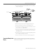
Terminal Block Assignments
No. Name Description