
Manual

Publication GMSI10-UM013D-EN-P - May 2010
72 Configuration Parameters
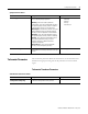
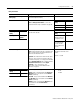
Tachometer Signal Processing Parameters
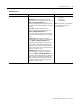
Fault Low The minimum, or most negative, expected DC
voltage from the transducer.
Volts
Note: A voltage reading outside this
range constitutes a transducer fault.
Fault High The maximum expected DC voltage from the
transducer.
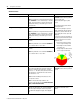
DC Bias Time Constant The time constant used for exponential averaging
(low pass filtering) of the transducer DC bias
measurement. The corner frequency for the low pass
filter is 1 / (2
π x DC Bias Time Constant). See
example table below.
Seconds
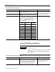
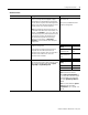
Tachometer Transducer Parameters
Parameter Name Description Values/Comments
Time Constant
(seconds)
-3dB Frequency
(Hz)
Settling Time
(seconds)
1 0.159 2.2
2 0.080 4.4
3 0.053 6.6
4 0.040 8.8
50.03211
6 0.027 13.2
7 0.023 15.4
8 0.020 17.6
9 0.018 19.8
10 0.016 22
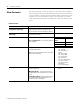
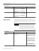
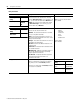
IMPORTANT
The tachometer is required for synchronous sampling and
the speed measurement.
If you are not using the tachometer channel, set the Pulses
Per Revolution to zero. This will disable the tachometer
measurement, and prevent the module from indicating a
tachometer fault.
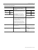
Tachometer Signal Processing Parameters
Parameter Name Description Values/Comments
Pulses Per Revolution The number of tachometer signal pulses per
revolution of the shaft (number of gear teeth). This
setting is useful if a proximity probe located over a
gear or shaft with a multi-toothed speed sensing
surface is used to generate the input signal.
Enter zero if you are not using the
tachometer channel to disable the
tachometer measurement.