USER MANUAL FOR SERIES B SMC™-Flex BULLETIN 150
Important User Information Because of the variety of uses for the products described in this publication, those responsible for the application and use of this control equipment must satisfy themselves that all necessary steps have been taken to assure that each application and use meets all performance and safety requirements, including any applicable laws, regulations, codes and standards.
European Communities (EC) Directive Compliance If this product has the CE mark it is approved for installation within the European Union and EEA regions. It has been designed and tested to meet the following directives. EMC Directive This product is tested to meet the Council Directive 89/336/EC Electromagnetic Compatibility (EMC) per EN/IEC 60947-4-2. This product is intended for use in an industrial environment.
Notes
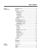
Table of Contents Chapter 1 Product Overview Other Related Documents ........................................................................... 1-1 Description .................................................................................................1-1 Operation ....................................................................................................1-2 Modes of Operation (Standard) ....................................................................1-2 Soft Start ......................
Lifting ......................................................................................................... 2-2 General Precautions .................................................................................... 2-3 Heat Dissipation .......................................................................................... 2-3 Enclosures .................................................................................................. 2-4 Mounting ..................................................
Current Limit Start ......................................................................................4-8 Dual Ramp Start ..........................................................................................4-9 Full Voltage Start .......................................................................................4-10 Linear Speed .............................................................................................4-10 Programming Parameters ...............................................
Fault Display ............................................................................................... 8-1 Clear Fault .................................................................................................. 8-2 Fault Buffer ................................................................................................. 8-2 Fault Codes ..........................................................................................8-3 Fault and Alarm Auxiliary Indication for Fault or Alarm ......
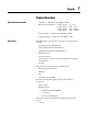
Chapter 1 Product Overview Other Related Documents Description • Quick Start — Publication 150-QS001_①-EN-P • Renewal Part Instructions — 41053-277-01 41053-328-01 41053-228-01 41053-367-01 • Selection Guide — Publication 150-SG009_①-EN-P • Application Guide — Publication 150-AT002_①-EN-P (5…85 A) (108…135 A) (201…480 A) (625…1250 A) The SMC™-Flex controller offers a full range of starting modes as standard: • Soft Start with Selectable Kickstart • Current Limit with Selectable Kickstart •
1-2 Product Overview Operation The SMC-Flex controller can operate standard squirrel-cage induction motors rated 1…1250 A or Star-delta (wye-delta) type motors rated 1.8…1600 A; up to 690V AC, 50/60 Hz. Depending upon the controller type ordered, the control power input can range from 100…240V AC to 24V AC/DC. Please verify voltage on product, before applying power. Modes of Operation (Standard) Soft Start ① This mode has the most general application.
Product Overview 1-3 Selectable Kickstart This feature provides a boost at startup to break away loads that require a pulse of high torque to get started. This is intended to provide a pulse of current that is selectable from 0…90% of locked rotor torque. Selectable kickstart is user-adjustable from 0.0…2.0 seconds. Figure 1.
Product Overview Dual Ramp Start ➀ This starting mode is useful on applications that have varying loads (and therefore varying starting torque requirements). Dual Ramp Start allows the user to select between two separate start profiles with separately adjustable ramp times and initial torque settings. Figure 1.
Product Overview 1-5 Preset Slow Speed This option can be used in applications that require a slow speed jog for general purpose positioning. Preset Slow Speed provides either 7% of base speed (low) or 15% of base speed (high) settings in the forward direction. Reverse can also be programmed and offers 10% of base speed (low) and 20% of base speed (high) settings. Figure 1.
1-6 Product Overview Linear Speed Acceleration ➀ The SMC-Flex has the ability to control the motor speed during starting and stopping maneuvers. A tach input (0…5V DC) is required to perform this start mode. The start time is selectable from 0…30 seconds and determines the time the motor will ramp from 0 speed to full speed. Kickstart is available with this option. Figure 1.
Product Overview 1-7 Soft Stop This option can be used in applications that require an extended stop time. The voltage ramp down time is user-adjustable from 0…120 seconds and is adjusted independently from the starting time. The load will stop when the output voltage drops to a point where the load torque is greater than the developed motor torque. Figure 1.
1-8 Product Overview Control Options The SMC-Flex controller offers the control options described below. Important: The options listed in this section are mutually exclusive and must be specified when ordering. An existing controller may be upgraded to another control option by replacing the control module. Consult your local Allen-Bradley distributor.
Product Overview SMB™ Smart Motor Braking Option This option can be used in applications that require reduced stopping times. The SMC-Flex controller incorporates a microprocessor-based system that applies braking current to a motor without any additional equipment. This option offers a user-adjustable braking current setting from 0% to 400% of the motor’s full load current rating. Further, it provides automatic shut-off at zero speed detection. Figure 1.
1-10 Product Overview Accu-Stop™ Option This option combines the benefits of the SMB Smart Motor Braking and Preset Slow Speed options. For general purpose positioning, the Accu-Stop option provides a brake from full speed to the preset slow speed setting, then brakes to stop. Figure 1.11 Accu-Stop Option ATTENTION ! Accu-Stop and Slow Speed with Braking are not intended to be used as an emergency stop. Refer to applicable standards for emergency stop requirements.
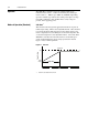
Product Overview Protection and Diagnostics 1-11 The SMC-Flex controller provides the protective and diagnostic features described below. Overload The SMC-Flex controller meets applicable requirements as a motor overload protective device. Thermal memory provides added protection and is maintained even when control power is removed. The built-in overload controls the value stored in Parameter 12, Motor Thermal Usage; an Overload Fault will occur when this value reaches 100%.
1-12 Product Overview Figure 1.13 Overload Trip Curves Class 15 Class 20 Class 30 100.0 1000.0 1000.0 1000.0 10.0 1.0 0.1 2 3 4 5 6 7 8 9 10 Multiples of FLC 10.0 100.0 10.0 1.0 1 2 3 4 1 Multiples of FLC 100.0 10.0 1.0 1.0 5 6 7 8 9 10 2 3 4 5 6 7 8 9 10 2 1 Multiples of FLC Approximate trip time time for for 3-phase 3-phasebalanced balanced Approximate trip condition from cold cold start. start.
Product Overview 1-13 Undervoltage ➀ Utilizing the undervoltage protection of the SMC-Flex, motor operation can be halted if a sudden drop in voltage is detected. The SMC-Flex controller provides an adjustable undervoltage trip setting from 0…99% of the programmed motor voltage. Trip delay time can be adjusted from 0…99 seconds. An alarm (pre-fault) indication level can be programmed to indicate the unit is getting close to faulting.
1-14 Product Overview Stall Protection and Jam Detection The SMC-Flex controller provides both stall protection and jam detection for enhanced motor and system protection. • Stall protection is user-adjustable from 0.0…10.0 seconds (in addition to the ramp time programmed). Figure 1.15 Stall Protection 600% Percent Full Load Current Programmed Start Time Stall Time (seconds) • An alarm (pre-fault) indication level can be programmed to indicate the unit is getting close to faulting.
Product Overview 1-15 Ground Fault In isolated or high impedance-grounded systems, core-balanced current sensors are typically used to detect low level ground faults caused by insulation breakdowns or entry of foreign objects. Detection of such ground faults can be used to interrupt the system to prevent further damage, or to alert the appropriate personnel to perform timely maintenance. The SMC-Flex’s ground fault detection capabilities require the use of external sensor.
1-16 Product Overview Ground Fault Trip The SMC-Flex will trip with a ground fault indication if: • No other fault currently exists • Ground fault protection is enabled • GF Inhibit Time has expired • GF Current is equal to or greater than the GF Trip Level for a time period greater than the GF Trip Delay Parameter 75, Gnd Flt Inh Time, allows the installer to inhibit a ground fault trip from occurring during the motor starting sequence and is adjustable from 0…250 seconds.
Product Overview 1-17 Thermistor/PTC Protection The SMC-Flex provides terminals 23 and 24 for the connection of positive temperature coefficient (PTC) thermistor sensors. PTC sensors are commonly embedded in motor stator windings to monitor the motor winding temperature. When the motor winding temperature reaches the PTC sensor’s temperature rating, the PTC sensor’s resistance transitions from a low to high value.
1-18 Product Overview • The resistance across terminals 23 and 24 is either greater than the relay’s response resistance or less than the short-circuit trip resistance. Excessive Starts/Hour The SMC-Flex controller allows the user to program the allowed number of starts per hour (up to 99). This helps eliminate motor stress caused by repeated starting over a short time period. Overtemperature The SMC-Flex controller monitors the temperature of the SCRs and Bypass by using internal thermistors.
Product Overview Metering 1-19 Power monitoring parameters include: • Three-phase current • Three-phase voltage • Power in kW • Power usage in kWH • Power factor • Motor thermal capacity usage • Elapsed time Notes: (1) Voltage measurement is not available during the braking operation of the SMB Smart Motor Braking, Accu-Stop, and Slow Speed with Braking control options. (2) The elapsed time and kWH values are automatically saved to memory every 12 hours.
1-20 Product Overview Communication A serial interface port (DPI) is provided as standard, which allows connection to the Bulletin 20-HIM LCD interface modules. Figure 1.19 DPI Location DPI ATTENTION ! Programming Two peripheral devices can be connected to the DPI. The maximum output current through the DPI is 280 mA. Setup is easy with the built-in keypad and three-line, sixteen character backlit LCD.
Product Overview Status Indication 1-21 Four programmable hard contact outputs are provided as standard. All auxiliary contacts are programmable for the following states: • Normal (N.O./N.C.) • Up-to-Speed (N.O./N.C.) • Alarm (N.O./N.C.) • Fault (N.O./N.C.) • Network Control (N.O./N.C.) • External Bypass (N.O.) Figure 1.
1-22 Notes Product Overview
Chapter 2 Installation Degree of Protection The SMC-Flex soft starters have an IP00 or IP2X protection rating, depending on the size. Taking into account the ambient conditions, the device must be installed in IP54 (Type 2) switchgear cabinets. Make sure that no dust, liquids, or conductive parts can enter the soft starter. Soft starter operation produces waste heat (heat loss). See Table 2.A or Specifications on page A-9, for details.
2-2 Lifting Installation For controllers rated 625…1250 A, the device should only be lifted from designated lifting points. The lifting points are designed to accept a ½ -13 threaded hoist ring capable of lifting 2500 pounds. These points are identified in Figure 2.1. Figure 2.
Installation General Precautions 2-3 In addition to the precautions listed throughout this manual, the following statements, which are general to the system, must be read and understood. ATTENTION ! ATTENTION ! ATTENTION ! ATTENTION ! Heat Dissipation The controller contains ESD- (electrostatic discharge) sensitive parts and assemblies. Static control precautions are required when installing, testing, servicing, or repairing the assembly.
2-4 Enclosures Installation The open-style design of the SMC-Flex controller requires that it be installed in an enclosure. The internal temperature of the enclosure must be kept within the range of 0…50°C. For Type 12 (IP54) enclosures, the following guidelines are recommended to limit the maximum controller ambient temperature. There should be a clearance of at least 15 cm (6 in.) above and below the controller. This area allows air to flow through the heatsink. Table 2.
Installation Mounting 2-5 All units are fan cooled. It is important to locate the controller in a position that allows air to flow vertically through the power module. The controller must be mounted in a vertical plane and have a minimum of 15 cm (6 in.) free space above and below the controller. When drilling or installing near the softstarter, make sure that adequate measures are taken to protect the device from dust and debris. See Figure 2.2. Figure 2.
2-6 Installation Figure 2.3 Dimensions: 5…85 A Controllers C F B E H D A 5…85 A Controller Unit A Width B Height C Depth D E F H Approx. Ship. Wt. mm 150.1 307 203.1 120 291 119.8 14.1 5.7 kg in. 5.91 12.09 8.00 4.72 11.46 4.72 0.56 12.6 lb. All dimensions are approximate and are not intended for manufacturing purposes. Consult your local Allen-Bradley distributor for complete dimension drawings.
Installation 2-7 Figure 2.4 Dimensions: 108…135 A Controllers F G E B C D A 108…135 A Controller Unit A Width B Height C Depth D E F G Approx. Ship. Wt. mm 196.4 443.7 212.2 166.6 367 129.5 26 15 kg in. 7.74 17.47 8.35 6.56 14.45 5.10 1.02 33 lb. All dimensions are approximate and are not intended for manufacturing purposes. Consult your local Allen-Bradley distributor for complete dimension drawings.
2-8 Installation Figure 2.5 Dimensions: 201…251 A Controllers 50.8 (2.0) 13.5 (.531) 24.9 (.980) 48 (1.890) 25 (.984) M10 X 1.5 #8-32 UNC-2B DETAIL AA SCALE 1.000 C 253.8 (9.992) 19.7 (.776) Ø11.5 (.453) F 157.25 (6.2) 6.4 (.250) 91.189 (3.59) Ø27.5 (1.083) G 164.126 (6.46) E SEE DETAIL AA 245.689 (9.67) B 560 (22.047) 504.1 (19.847) 80 (3.15) 152.749 (6.01) 79.811 (3.14) H I 44.311 (1.74) D A 201…251 A Controller 150 (5.906) Ø13 (.513) 225 (8.858) 40.9 (1.
Installation 2-9 Figure 2.6 Dimensions: 317…480 A Controllers 63.5 (2.50) 32.74 (1.29) 17 (.67) 48 (1.89) C 22.5 (.89) 276.5 (10.89) M12 x 1.75 #8 - 32 UNC - 2B 30.5 (1.20) F 182.25 (7.18) 12.522 (.49) 6.35 40.9 (1.6) 317…480 A Controller Unit A Width B Height C Depth D E F G H I Approx. Ship. Wt. mm 290 600 276.5 200 539.18 182.25 104.5 55.5 103.5 45.8 kg in. 11.42 23.62 10.89 7.87 21.23 7.18 4.11 2.19 4.07 101 lb.
2-10 Installation Figure 2.7 Dimensions: 625…780 A Controllers 4.00 [ 101,6 2.00 [ 50,8 ] 1.00 [ 25,4 ] ] .78 [ 19,8 ] 1.20 [ 30,5 .39 [ 10 ] ] Ø.531 #8-32 UNC-2B [ 13,49 ] 3X DETAIL A 4X 2.75 [ 69,8 4X 3.00 [ 76,2 7.00 [ 177,8 8.25 [ 209,5 ] ] C ] Ø.734 [ ] 18,64 13.63 [ 346,2 Ø.500 ] [ 12,7 2X .25 [ 6,4 ] 8.46 [ 214,9 ] ] F ] SEE DETAIL A B 41.00 [ 1041,4 38.45 [ 976,6 ] ] E 29.02 [ 737 ] 23.39 [ 594,1 19.54 [ 496,3 ] ] 14.54 [ 369,4 ] 13.
Installation 2-11 Figure 2.8 Dimensions: 970…1250 A Controllers 5.00 [ 127 ] 2.50 [ 63,5 ] 1.25 [ 31,8 ] .74 [ 18,8 ] .28 [ 7,2 ] 1.20 [ 30,5 ] #8-32 UNC-2B Ø.531 .531 [ 13,49 ] 3X DETAIL A 7.00 [ 177,8 ] C 8.25 [ 209,5 ] 4X 2.00 [ 50,8 ] 13.63 [ 346,2 ] 8.46 [ 214,9 ] 2X .25 [ 6,4 ] Ø.500 .500 [ 12,7 ] Ø.734 .734 [ 18,64 ] 4X 2.25 [ 57,1 ] F SEE DETAIL A B 41.00 [ 1041,4 ] 38.45 [ 976,6 ] 29.02 [ 737 ] E 23.39 [ 594,1 ] 19.54 [ 496,3 ] 14.54 [ 369,4 ] 13.86 [ 351,9 ] G 7.
2-12 Installation Power Factor Correction Capacitors The controller can be installed on a system with power factor correction (PFC) capacitors. The capacitors must be located on the line side of the controller. This must be done to prevent damage to the SCRs in the SMC-Flex controller. When discharged, a capacitor essentially has zero impedance. For switching, sufficient impedance should be connected in series with the capacitor bank to limit the inrush current.
Installation Protective Modules Protective modules containing metal oxide varistors (MOVs) can be installed on controllers rated 5…1250 A and 200…600V, to protect the power components from electrical transients. The protective modules clip voltage transients generated on the lines to prevent such surges from damaging the SCRs. ATTENTION ! Motor Overload Protection 2-13 When installing or inspecting the protective module, make sure that the controller has been disconnected from the power source.
2-14 Installation Electromagnetic Compatibility (EMC) ATTENTION ! This product has been designed for Class A equipment. Use of the product in domestic environments may cause radio interference, in which case, the installer may need to employ additional mitigation methods. The following guidelines are provided for EMC installation compliance. Enclosure Install the product in a grounded metal enclosure.
Chapter 3 Wiring Terminal Locations The SMC-Flex controller wiring terminal locations are shown in Figure 3.1 and Figure 3.2. Make wiring connections as indicated in the typical connection diagrams. Incoming three-phase power connections are made to terminals L1/1, L2/3, and L3/5. Load connections to Line motors are made to T1/2, T2/4, and T3/6, while load connections to Wye-Delta motors are made to T1/2, T2/4, T3/6, T4/8, T5/10, and T6/12. Figure 3.
3-2 Wiring Figure 3.2 Wiring Terminal Locations (108…480 A) 1 5 4 3 3 Table 3.
Wiring 3-3 Figure 3.3 Wiring Terminal Locations (625…1250 A) 1 3 2 Table 3.B Power Structure Wiring Terminal Locations 1 Incoming Line Terminations 2 Line Motor Connections 3 Terminal Block CP1 - Common Control Power Connections (Fans, Contactors, and Control Modules) The SMC-Flex product has an integrated mechanical run contactor on each phase of the motor to minimize heat generation during run time. These contacts are pulled in sequentially in the 108…1250 A units.
3-4 Wiring ATTENTION ! Failure of solid state power switching components can cause overheating due to a single-phase condition in the motor. To prevent injury or equipment damage, the following is recommended: Use of an isolation contactor or shunt trip type circuit breaker on the line side of the SMC. This device should be capable of interrupting the motor’s lock rotor current. Connection of this isolation device to an auxiliary contact on the SMC-Flex.
Wiring 3-5 SMC-Flex IC 5/L3 6/T3 10/T5 IC 3/L2 4/T2 M 3~ 8/T4 IC 1/L1 2/T1 12/T6 Power Lugs Power lugs are required for devices rated 108..1250 A. In some cases these lugs are sold in kits. Each kit contains three lugs. The number and type of lugs required is listed in the following tables. Table 3.C lists the recommended lugs for the SMC when configured as a line connection. Table 3.D lists the recommended lugs when using the SMC Flex with a delta connection.
3-6 Wiring Table 3.C SMC Rating Lug Kit Cat. No. Wire Strip Length Conductor Range 5…85 A — 18…20 mm 108…135 A 199-LF1 201…251 A SMC-Flex 5…1250 A, Line Connection Lug Information Max. No. Lugs/Pole Tightening Torque Line Side Load Side Wire — Lug Lug — Busbar 2.5…85 mm2 (#14…3/0 AWG) — — 11.3 N•m (100 lb.-in.) — 18…20 mm 16…120 mm2 (#6…250 MCM) 1 1 31 N•m (275 lb.-in.) 23 N•m (200 lb.-in.) 199-LF1 18…20 mm 16…120 mm2 (#6…250 MCM) 2 2 31 N•m (275 lb.-in.) 23 N•m (200 lb.
Wiring Control Power 3-7 Control Wiring Refer to the product nameplate for control terminal wire capacity and tightening torque requirements. Each control terminal will accept a maximum of two wires. Refer to the product nameplate prior to applying control power. Depending on the specific application, additional control circuit transformer VA capacity may be required.
3-8 Wiring Figure 3.6 230V Control Undervoltage Relay Settings for 625…1250 A Devices SEE NAMEPLATE FOR STATUS 115% LED PICK-UP % NOMINAL VOLTAGE 10 85% SEC. 240 0.1 TIME DELAY PICK-UP 220 10 NOMINAL VOLTAGE 208 SEC. 95% 0.1 TIME DELAY DROP-OUT DROP OUT % PICK-UP 0% GENERAL NOTES: 1. SET ALL RELAY POTENTIOMETERS PER ILLUSTRATION.
Wiring 3-9 Figure 3.7 Internal Wiring and 230V Control Undervoltage Relay Connection Diagram for 625…1250 A Devices 6 5 4 3 See Figure 3.6 for setting information. UV.
Wiring Figure 3.
Wiring 3-11 Control Wire Specifications Table 3.F provides the control terminal wire capacity, the tightening torque requirements, and the wire strip length. Each control terminal will accept a maximum of two wires. Table 3.F Control Wiring and Tightening Torque Wire Size 0.75…2.5 mm2 Fan Power (#18…14 AWG) Torque Wire Strip Length 0.6 N•m (5 lb.-in.) 5.6…8.6 mm (0.22…0.34 in.) Controllers rated 5…1250 A have heatsink fan(s). Refer to Table 3.
3-12 Wiring Control Terminal Designations As shown in Figure 3.10, the SMC-Flex controller contains 24 control terminals on the front of the controller. Figure 3.
Wiring Standard Controller Wiring Diagrams Figure 3.11 through Figure 3.22 show typical wiring for the SMC-Flex controller. Figure 3.
3-14 Wiring Figure 3.12 Typical Wiring Diagram for Two-Wire Control with Stopping Control (No DPI Control) L1/1 T1/2 L2/3 T2/4 L3/5 T3/6 3-Phase M ➀ Input Power ➀ ➀ Branch SMC-Flex Controller Protection ➀ ➀ Two-Wire Device ➀ ➁ 11 12 13 14 15 16 17 18 SMC-Flex Control Terminals 23 24 PTC Input 25 26 TACH Input 19 20 21 22 33 34 Aux #1 27 28 Ground Fault 29 30 Aux #2 31 32 Aux #3 Aux #4 ➀ Customer supplied.
Wiring Figure 3.13 Typical Wiring Diagram for Dual Ramp Applications L1/1 T1/2 L2/3 T2/4 L3/5 T3/6 3-Phase M ➀ Input Power ➀ ➀ Branch SMC-Flex Controller Protection ➀ ➀ Stop Ramp 1 Start Ramp 2 ➀ ➀ ➀ ➁ 11 12 13 14 15 16 17 18 SMC-Flex Control Terminals 23 24 PTC Input 25 26 19 20 21 22 33 34 Aux #1 27 TACH Input 28 Ground Fault 29 30 Aux #2 31 32 Aux #3 Aux #4 ➀ Customer supplied.
3-16 Wiring Figure 3.14 Typical Wiring Diagram for Start-Stop Control via DPI Communications Note: Use this wiring diagram when start-stop will come from either a Bulletin 20-HIM LCD interface module or a Bulletin 20-COMM communication module connected to the SMC-Flex. Note: Logic mask must be properly configured, see Chapter 8.
Wiring Figure 3.15 Typical Wiring Diagram for Retrofit Applications L1/1 T1/2 L2/3 T2/4 L3/5 T3/6 3-Phase Input Power ➀ ➀ Branch Existing Motor Starter ➀ Protection ➀ M ➀ SMC-Flex Controller ➁ ➀ OL ➀ M ➀ Start Stop ➀ M ➀ ➀ ➂ 11 12 13 14 15 16 17 18 SMC-Flex Control Terminals 23 24 PTC Input 25 26 TACH Input 19 20 21 22 33 34 Aux #1 27 28 Ground Fault 29 30 Aux #2 ➀ Customer supplied.
3-18 Wiring Figure 3.16 Typical Wiring Diagram for Isolation Applications (DPI also) L1/1 T1/2 L2/3 T2/4 L3/5 T3/6 3-Phase M ➀ Input Power ➀ ➀ Branch Isolation Contactor (IC) Protection ➀ ➀ ➀ SMC-Flex Controller IC ➀ Stop ➀ Start ➀ ➁ 11 12 13 14 15 16 17 18 SMC-Flex Control Terminals 23 24 25 PTC Input 26 TACH Input 27 19 20 21 22 33 34 Aux #1 28 Ground Fault 29 30 Aux #2 31 32 Aux #3 Aux #4 ➂ ➀ Customer supplied.
Wiring 3-19 Figure 3.17 Typical Wiring Diagram for Shunt Trip Applications L1/1 T1/2 L2/3 T2/4 L3/5 T3/6 3-Phase M ➀ Input Power ➀ ➀ Branch Protection SMC-Flex Controller ➀ ➀ ST ➀ Stop Start ➀ ➀ ➁ 11 12 13 14 15 16 17 18 SMC-Flex Control Terminals 23 24 PTC Input 25 26 TACH Input 19 20 21 22 33 34 Aux #1 27 28 Ground Fault 29 30 ➂ Aux #2 31 32 Aux #3 Aux #4 ➀ Customer supplied.
3-20 Wiring Figure 3.18 Typical Wiring Diagram for Single-Speed Reversing Applications F L1/1 T1/2 L2/3 T2/4 L3/5 T3/6 3-Phase Input Power ➀ Branch Protection R SMC-Flex Controller Reversing Contactors ➀ ➀ M ➀ ➀ ➀ OFF ➀ FOR REV E-Stop F➀ ➃ R ➀ R F ➀ R ➀ F ➀ ➁ 11 12 13 14 15 16 17 18 SMC-Flex Control Terminals 24 23 25 PTC Input 26 TACH Input 27 19 20 21 22 33 34 Aux #1 28 Ground Fault 29 30 Aux #2 31 32 Aux #3 Aux #4 ➀ Customer supplied.
Wiring 3-21 Figure 3.19 Typical Wiring Diagram for Two-speed Applications Two-Speed Motor Starter ➀ H ➁ L L1/1 T1/2 L2/3 T2/4 L3/5 T3/6 3-Phase H➁ Input Power ➃ H ➀ Branch Protection SMC-Flex Controller M ➀ ➀ ➀ Stop ➀ ➀ High Low ➀ ➀ H➀ LOL ➀ HOL ➀ L ➀ L L➀ H H ➀ L➀ 1 sec. H ➀ 1 sec.
3-22 Wiring Figure 3.20 Typical Wiring Diagram for SMC-Off-Bypass Control L1/1 T1/2 L2/3 T2/4 L3/5 T3/6 3-Phase M ➀ Input Power ➀ Branch ➀ Protection SMC-Flex Controller ➀ ➀ BC SMC Off Bypass Bypass ➀ OL ➀ Bypass Connector (BC) X Stop ➀ Start ➀ ➀ X ➁ 11 12 13 14 15 16 17 18 SMC-Flex Control Terminals 23 24 PTC Input 25 26 TACH Input 19 20 21 22 33 34 Aux #1 27 28 Ground Fault 29 30 Aux #2 31 32 Aux #3 Aux #4 ➀ Customer supplied.
Wiring 3-23 Figure 3.21 Typical Wiring Diagram for Hand-Off-Auto Control with Stop Option and Start/Stop Push Buttons Control Power ➁ C ➀ H Start ➀ Stop ➀ A➀ C➀ ➀ Auto Device C➀ 11 12 13 14 15 16 17 18 SMC-Flex Control Terminals 23 24 PTC Input 25 26 TACH Input 19 20 21 22 33 34 Aux #1 27 28 Ground Fault 29 30 Aux #2 31 32 Aux #3 Aux #4 ➀ Customer supplied. ➁ Refer to the controller nameplate to verify the rating of the control power input voltage.
3-24 Wiring Soft Stop, Pump Control, and SMB Smart Motor Braking Figure 3.22 through Figure 3.25 show the different wiring for the Soft Stop, Pump Control, and SMB Smart Motor Braking options. Figure 3.22 Typical Wiring Diagram Control Power ➂ Stop Start Option Stop ➀ ➁ 11 12 13 14 15 16 17 18 SMC-Flex Control Terminals 23 24 PTC Input 25 26 TACH Input 19 ➀ ➀ 20 21 22 33 34 Aux #1 27 28 Ground Fault 29 30 Aux #2 31 32 Aux #3 Aux #4 ➀ Customer supplied.
Wiring 3-25 Figure 3.23 Typical Retrofit Wiring Diagram Control Power ➂ ➀➁ OL M ➀ Stop ➀ Start Option Stop ➀ ➀➃ 11 12 13 14 15 16 17 18 SMC-Flex Control Terminals 23 24 PTC Input 25 26 TACH Input 19 20 21 22 33 34 Aux #1 27 28 29 Ground Fault 30 Aux #2 31 32 Aux #3 Aux #4 ➄ ➀ Customer supplied. ➁ Overload protection should be disabled in the SMC-Flex controller. ➂ Refer to the controller nameplate to verify the rating of the control power input voltage.
3-26 Wiring Figure 3.24 Typical Wiring Diagram for Applications Requiring an Isolation Contactor Control Power ➁ IC ➀ Stop Option Stop 11 12 13 Start ➀➂ 14 15 16 17 18 SMC-Flex Control Terminals 24 23 PTC Input 25 26 TACH Input 19 ➀ ➀ 20 21 22 33 34 Aux #1 27 28 Ground Fault 29 30 Aux #2 31 32 Aux #3 Aux #4 ➃ ➀ Customer supplied. ➁ Refer to the controller nameplate to verify the rating of the control power input voltage.
Wiring 3-27 Figure 3.25 Typical Wiring Diagram for Hand-Off-Auto (DPI) Control (Soft Stop, Braking, and Pump Control Only) L1/1 T1/2 L2/3 T2/4 L3/5 T3/6 3-Phase M ➀ Input Power ➀ ➀ Branch SMC-Flex Controller Protection ➀ ➀ Control Power 100-240 VAC A ➀ X00 H X00 00X 11 12 13 14 15 16 17 18 SMC-Flex Control Terminals 24 23 PTC Input ➀ 25 26 TACH Input Customer supplied.
3-28 Wiring Preset Slow Speed Figure 3.26 and Figure 3.27 show the different wiring for the Preset Slow Speed. Figure 3.26 Typical Wiring Diagram for the Preset Slow Speed Control Power ➁ Stop Option Command Start ➀ ➂ 11 12 13 14 15 16 17 18 SMC-Flex Control Terminals 23 24 PTC Input 25 19 ➀ ➀ 20 21 22 33 34 Aux #1 27 26 TACH Input 28 Ground Fault 29 30 Aux #2 31 32 Aux #3 Aux #4 ➀ Customer supplied.
Wiring 3-29 Figure 3.27 Typical Slow Speed Wiring Diagram for Hand-Off-Auto (DPI) Control L1/1 T1/2 L2/3 T2/4 L3/5 T3/6 3-Phase M ➀ Input Power ➀ ➀ Branch Protection ➀ ➀ H SMC-Flex Controller A Hand Stop ➀ Hand Start ➀ Option Command ➀ ➁ ➂ 11 12 13 14 15 16 17 18 SMC-Flex Control Terminals 23 24 PTC Input 25 26 TACH Input 19 20 21 22 33 34 Aux #1 27 28 Ground Fault 29 30 Aux #2 31 32 Aux #3 Aux #4 ➃ ➀ Customer supplied. ➁ Slow Speed.
3-30 Wiring Slow Speed with Braking Figure 3.28 shows the wiring for the Slow Speed with Braking option. Figure 3.28 Typical Wiring Diagram for the Slow Speed with Braking with an Isolation Contactor #ONTROL 0OWER )# 3TOP "RAKE 3TART 3LOW 3PEED 3-# &LEX #ONTROL 4ERMINALS 04# )NPUT 4!#( )NPUT !UX 'ROUND &AULT !UX !UX !UX ➂ ➀ Customer supplied.
Wiring Sequence of Operation 3-31 Figure 3.29 through Figure 3.34 show the different operation sequences for the Soft Stop, Preset Slow Speed, Pump Control, SMB Smart Motor Braking, Accu-Stop, and Slow Speed with Braking options. Figure 3.
3-32 Wiring Figure 3.
Wiring 3-33 Figure 3.
3-34 Wiring Figure 3.
Wiring 3-35 Figure 3.33 Accu-Stop Sequence of Operation 100 % Braking Motor Speed Slow Speed Braking Coast-to-rest Slow Speed Slow Speed Start Run Accu-Stop Time (seconds) Push Buttons Start Closed Open Stop Closed Open ➀ Accu-Stop Closed Open Slow Speed Braking Auxiliary Contacts Normal If Coast-to-rest Selected Up-to-speed ➀ When Accu-Stop push button is closed, start/stop function is disabled.
3-36 Wiring Figure 3.
Wiring 3-37 Figure 3.35 Protective Module PRO TEC TIV EM ODU LE MAX . LIN E V MADE OLT IN AGE U.S.A There are two general situations that may occur which would indicate the need for using the protective modules. 1. Transient spikes may occur on the lines feeding the SMC-Flex controller (or feeding the load from the SMC-Flex controller). Spikes are created on the line when devices are attached with current-carrying inductances that are open-circuited.
3-38 Wiring Multi-motor Applications The SMC-Flex controller will operate with more than one motor connected to it. To size the controller, add the total nameplate amperes of all of the connected loads. The stall and jam features should be turned off. Separate overloads are still required to meet the National Electric Code (NEC) requirements. Note: The SMC-Flex controller’s built-in overload protection cannot be used in multi-motor applications. Figure 3.
Wiring SMC-Flex Controller as a Bypass to an AC Drive 3-39 By using the controller as shown in Figure 3.37, a soft start characteristic can be provided in the event that an AC drive is nonoperational. Note: A controlled acceleration can be achieved with this scheme, but speed control is not available in the bypass mode. Figure 3.37 Typical Application Diagram of a Bypass Contactor for an AC Drive AF ➁ AF ➁ O.L.
3-40 Wiring SMC-Flex Controller with a Bulletin 1410 Motor Winding Heater Figure 3.38 Typical Application Diagram of SMC-Flex Controller with a Bulletin 1410 Motor Winding Heater IC ➀ L1/1 T1/2 L2/3 T2/4 O.L. ➀ 3-Phase M ➀ Input Power L3/5 T3/6 SMC-Flex Controller ➁ ➀ HC Bulletin 1410 MWH ➀ ➀ Customer supplied. ➁ Overload protection is included as a standard feature of the SMC-Flex controller.
Chapter 4 Programming Overview This chapter provides a basic understanding of the programming keypad built into the SMC-Flex controller. This chapter also describes programming the controller by modifying the parameters. Keypad Description The keys found on the front of the SMC-Flex controller are described below. Escape Exit a menu, cancel a change to a parameter value, or acknowledge a fault/alarm. Select Select a digit, select a bit, or enter edit mode in a parameter screen.
4-2 Programming Figure 4.
Programming 4-3 Figure 4.
4-4 Programming Table 4.A Parameter No.
Programming Password 4-5 The SMC-Flex controller allows the user to limit access to the programming system through password protection. This feature is disabled with a factory-set default of 0. To modify the password, complete the procedure below. Description — Action — Display 0.0 Amps 0 Volt 0 %MTU Main in Menu Preferences Diagnostics 1. Press the ESC key to go from the status display to the Main menu. 2. Scroll with the Up/Down keys until the Preferences option is highlighted.
4-6 Programming Parameter Management Before you begin programming, it’s important to understand how the controller memory is: • structured within the SMC-Flex controller • used on power-up and during normal operation Refer to Figure 4.3 and the explanations below. Figure 4.3 Memory Block Diagram EEPROM RAM Esc ROM Sel Random Access Memory (RAM) This is the work area of the controller after it is powered up. The SMC-Flex uses an Auto Store feature when programming parameters.
Programming Parameter Modification 4-7 All parameters are modified using the same method. The basic steps to performing parameter modification are described below. Notes: (1) Parameter values modified while the motor is operating are not valid until the next time that operation occurs. (2) If the password is set, parameters cannot be adjusted without logging in. (3) Use the Sel key to highlight a single digit. 1. 2.
4-8 Programming Soft Start The following parameters are specifically used to adjust the voltage ramp supplied to the motor. Parameter Starting Mode This must be programmed for Soft Start. Soft Start Ramp Time ➀ This programs the time period that the controller will ramp the output voltage up to full voltage from the Initial Torque level programmed. 0…30 s Initial Torque The initial reduced output voltage level for the voltage ramp to the motor is established and adjusted with this parameter.
Programming Dual Ramp Start 4-9 The SMC-Flex controller provides the user with the ability to select between two Start settings. The parameters below are available in the Set Up programming mode. To obtain Dual Ramp control, Ramp #1 is located in the Basic Set Up and Ramp #2 is located in the Option 2 Input (Dual Ramp). Parameter Option Set Up The user must select the Set Up programming mode to obtain access to the Dual Ramp parameters. — Basic Set Up/Starting Mode Set Up as stated in previous pages.
4-10 Programming Full Voltage Start The SMC-Flex controller may be programmed to provide a full voltage start (output voltage to the motor reaches full voltage within 1/4 second) with the following programming: Parameter Starting Mode This must be programmed for Full Voltage. Linear Speed Option Full Voltage The SMC-Flex provides the user the ability to control the motor speed during starting and stopping maneuvers. A tach input is required as specified in Linear Speed Acceleration on page 1-6.
Programming Programming Parameters 4-11 The following table provides the option-specific parameters that are provided with each control option. These parameters are in addition to those already discussed in the Basic Set Up and Metering groups. Diagrams supporting the options described below are shown later in this chapter. Option Parameter Range Standard Soft Stop Preset Slow Speed SMC Option This parameter identifies the type of control present and is not user programmable.
4-12 Programming Option Parameter Range Pump Control Pump Control SMC Option This parameter identifies the type of control present and is not user programmable. Pump Control Pump Stop Time Allows the user to set the time period for the pump stopping function. 0…120 s Starting Mode Allows the user to program the SMC-Flex controller for the type of starting that best fits the application.
Programming ➀ 4-13 Option Parameter Range Slow Speed with Braking SMC Option This parameter identifies the type of control present and is not user programmable. Braking Control Slow Speed Select Allows the user to program the slow speed that best fits the application. Low:7% High:15% Slow Accel Current Allows the user to program the required current to accelerate the motor to slow speed operation.
4-14 Programming Basic Set Up The Basic Set Up programming group provides a limited parameter set, allowing quick start-up with minimal adjustment. If the user is planning to implement some of the advanced features (e.g., Dual Ramp, or Preset Slow Speed), then the Setup programming group should be selected. It provides all the Basic Set Up parameter set plus the advanced set. Parameter Option SMC Option Displays the type of controller. This is factory set and not adjustable.
Programming ATTENTION ! Motor Protection 4-15 For overload protection, it is critical that the data be entered as it appears on the motor nameplate. While the Basic Set Up group allows the user to get started with a minimum number of parameters to modify, the Motor Protection group allows full access to the SMC-Flex controller’s powerful parameter set. Following is a listing of the additional setup parameters provided. Note: The majority of parameters have a Fault and an Alarm setting.
4-16 Programming Example Settings Undervoltage ➀ With Line Voltage programmed for 480V and the Undervoltage level programmed for 80%, the trip value is 384V. Overvoltage ➀ With Line Voltage programmed for 240V and the Overvoltage level programmed for 115%, the trip value is 276V. Jam ➁➂ With Motor FLC programmed for 150 A and the Jam level programmed for 400%, the trip value is 600 A. Underload ➁ With Motor FLC programmed for 90 A and the Underload level programmed for 60%, the trip value is 54 A.
5 Chapter Metering Overview While the SMC-Flex controller operates your motor, it also monitors several different parameters, providing a full function metering① package. Viewing Metering Data To access the metering information, follow the procedure below. Description — Action — ##.# Amps ### Volt ## %MTU Esc 1. Press any of the following keys to access the Main Menu. 2. Scroll with the Up/Down keys until the Parameter option is shown. 3. Press the Enter key to select the Parameter option.
5-2 Metering Description 7. Scroll through the Metering parameters with the Up/Down keys to access the desired information. Press the Enter key to view that parameter. Action Display F GP : Volts Phase A-B ### P# 1 F GP : Volts Phase B-C ### P# 2 F GP : Volts Phase C-A ### P# 3 F GP : Current Phase A ##.# P# 4 Amps F GP : Current Phase B ##.# Amps Volt Volt Volt P# 5 F GP : Current Phase C ##.# P# 6 Amps F GP : Watt Meter P# 7 ##.# KW F GP : Kilowatt Hours ##.
Chapter 6 Optional HIM Operation Overview The SMC-Flex controller offers a variety of unique control options that provide enhanced motor starting and stopping capabilities. (See chapter 1 for brief descriptions of each option.) Note: Only one option can reside in a controller. Human Interface Module The control buttons available with the Bulletin 20-HIM LCD Human interface modules are compatible with the SMC-Flex controller’s control options.
6-2 Optional HIM Operation Option Action Operation I The green start button, when pressed, will commence motor acceleration to full speed. Pump Control Pump Control O The red stop button, when pressed, will provide a coast stop, and/or reset a fault. Jog The jog button, when pressed, will initiate a pump stop maneuver. I The green start button, when pressed, will commence motor acceleration to full speed.
Chapter 7 Communications Overview The SMC-Flex provides advanced communications capabilities that allow it to be started and stopped from multiple sources as well as provide diagnostic information through the use of communication interfaces. The SMC-Flex uses the DPI method of communication, therefore all standard DPI communication interfaces used by other devices (i.e., PowerFlex™ Drives) can be used in the SMC-Flex. ScanPort devices are not supported by the SMC-Flex.
7-2 Communications Human Interface Module The SMC-FLEX controller can be programmed with the built-in keypad and LCD display or with our optional Bulletin 20-HIM LCD human interface modules. Parameters are organized in a three-level menu structure and divided into programming groups. Note: Node addressing of the DPI communication card can be programmed via software or a hand-held DPI HIM. The onboard HIM cannot be used to address the communication card.
Communications 7-3 The control panel provides the operator interface to the controller. I O Jog Start The green start button, when pressed, will begin motor operation. (Proper setup of the HIM port is required.) Stop The red stop button, when pressed, will halt motor operation and/or reset a fault. Jog The jog button is active only when a control option is present. Pressing the jog button will initiate the option maneuver (for example: Pump Stop).
7-4 Communications Connecting the Human Interface Module to the Controller Figure 7.1 shows the connection of the SMC-Flex controller to a human interface module. Table 7.C provides a description of each port. Note: The SMC-Flex only supports the use of DPI communication modules and DPI HIM LCD Modules. Scanport devices are not supported by the SMC-Flex. See Figure 3.14 on page 3-16 for the control wiring diagram that enables start-stop control from a human interface module. Figure 7.
Communications 7-5 To enable motor control from a connected human interface module or communication module, you must take the following programming steps: 1. Disconnect the HIM and allow to power down. 2. Reconnect the HIM. On Initializing screen, the bottom right corner of LCD shows Port X. Note this port number. 3. Go to Logic Mask, found as follows: Main Menu: Parameter/Communications/Comm Mask/Logic Mask 4. Set b0X equal to 1 (where X is the port number noted in step 2).
7-6 Communications If enabling control from the built-in SMC-Flex programmer, the Logic Mask must be set as follows: Table 7.
Communications Default Input/Output Configuration 7-7 The default configuration for I/O is 4 bytes in and 4 bytes out (TX = 4 bytes, RX = 4 bytes). The total size may very when used with a communication card. The default configuration is arranged according to the following table. Table 7.
7-8 Communications SMC — Flex Bit Identification Table 7.
Communications Table 7.
7-10 Communications Display Text Unit Equivalents Some parameters have text descriptions when viewed from a HIM or through a communication software program such as RSNetworx™. When receiving or sending information from a PLC each text description has a numerical equivalent. Table 7.I has an example of Parameter 44, Overload Class, and the appropriate relationship between the text descriptor and the equivalent value. This relationship is identical for other similar parameters located in Appendix B.
Chapter 8 Diagnostics Overview This chapter describes the fault diagnostics of the SMC-Flex controller. Further, this section describes the conditions that cause various faults to occur. Protection Programming Many of the protective features available with the SMC-Flex controller can be enabled and adjusted through the programming parameters provided. For further details on programming, refer to the Motor Protection section in Chapter 4, Programming.
8-2 Clear Fault Diagnostics You can clear a fault using any of several methods: • Program the SMC-Flex controller for a Clear Fault, which can be found in Main Menu/Diagnostics/Faults. • If a human interface module is connected to the controller, press the Stop button. Note: A stop signal from HIM will always stop the motor and clear the fault regardless of Logic Mask. • If a RESET push button is present, the N.O. push button auxiliary contact can be connected to Option Input #2 (terminal 15).
Diagnostics 8-3 Fault Codes Table 8.A provides a complete cross-reference of the available fault codes and corresponding fault descriptions. Table 8.
8-4 Diagnostics Fault Definitions Table 8.B Table 8.B shows the fault definitions for the SMC-Flex. Fault Definitions Fault Description Line Loss F1, F2, F3 The SMC-Flex can determine if a line connection has been lost, and will indicate this accordingly. Shorted SCR Shorted SCRs will be detected and starting will be prohibited by the SMC-Flex. Open Gate Open gate indicates that an abnormal condition that causes faulty firing (e.g., open SCR gate) has been sensed during the start sequence.
Chapter 9 Troubleshooting Introduction For safety of maintenance personnel as well as others who might be exposed to electrical hazards associated with maintenance activities, follow the local safety related work practices (for example, the NFPA 70E, Part II in the United States). Maintenance personnel must be trained in the safety practices, procedures, and requirements that pertain to their respective job assignments.
9-2 Troubleshooting The following flowchart is provided to aid in quick troubleshooting. Figure 9.1 Troubleshooting Flowchart YES Fault Displayed? NO Define Nature of Trouble Motor rotates but does not accelerate to full speed Motor will not start — no output voltage to motor Table 9.A See See10.C Table Table 9.C on page 10-4 See See Table 10.B Table 9.B on page 10-4 See See10.A Table Table 9.A on page 10-3 Motor stops while running See See10.D Table Table 9.
Troubleshooting Table 9.
9-4 Troubleshooting Table 9.
Troubleshooting Starting • Mechanical problems • Inadequate Current Limit setting Failed control module • Table 9.D • • • • 9-5 Check for binding or external loading and correct Check motor Adjust the Current Limit Level to a higher setting Replace control module Motor Stops While Running Display Possible Cause Possible Solutions Fault displayed • See fault description • See Table 10.
9-6 Troubleshooting Motor stops too slowly with Soft Stop option • • • Stopping time setting Misapplication Fluid surges with pumps still occur with the Soft Stop option • Misapplication • • • Motor overheats • Duty cycle • • Motor short circuit • Winding fault • • • Verify the programmed stopping time and correct if necessary The Soft Stop option is intended to extend the stopping time for loads that stop suddenly when power is removed from the motor.
Troubleshooting Power Module Check 9-7 If a power module needs to be checked, use the applicable procedure that follows. ATTENTION ! ATTENTION ! To avoid shock hazard, disconnect main power before working on the controller, motor, or control devices such as Start/Stop push buttons. Make sure that wires are properly marked and programmed parameter values are recorded. Shorted SCR Test 1. Using an ohmmeter, measure the resistance between the line and load terminals of each phase on the controller.
9-8 Troubleshooting
Appendix A Specifications Functional Design Standard Features Installation Setup Communications Starting and Stopping Modes Protection and Diagnostics Metering Alarm Contact Status Indication Auxiliary Contacts Power Wiring Control Wiring Keypad Software Standard squirrel-cage induction motor or a Wye-Delta, six-lead motor. 2- and 3-wire control for a wide variety of applications. Front keypad and backlit LCD display.
A-2 Specifications Electrical Ratings Device Rating UL/CSA/NEMA IEC Power Circuit 480V Rated Operation Voltage 600V 690V Rated Insulation Voltage Rated Impulse Voltage Dielectric Withstand Repetitive Peak Inverse Voltage Rating Operating Frequency Utilization Category Protection Against Electrical Shock DV/DT Protection Transient Protection 480V 600V 690V 480V 600V 690V 480V 600V 690V 480V 600V 690V All 5…480 A 625…1250 A 5…85 A 108…480 A 625…1250 A 480V & 600V 690V 480V & 600V 690V 200…480V AC
Specifications A-3 Short Circuit Protection SCPD Performance 200…600V Protection Type SCCR List ➀ Line Device Operational Current Rating (A) Delta Device Operational Current Rating (A) 5 25 43 60 85 108 135 201 251 317 361 480 625 780 970 1250 8.7 43 74 104 147 187 234 348 435 549 625 831 850 900 1200 1600 Non Time-Delay Fuse Max. Std. Max. Std.
A-4 Specifications Power Requirements 120… 240V AC 24V AC Control Module, 1…480 A Control Module, 625…1250 A Heatsink Fan(s) (A) ➀ Transformer 75 VA Transformer 130 VA Inrush Current 5A Inrush Time 250 ms 24V DC Transient Watts 60 W Transient Time 500 ms Steady State Watts 24 W Minimum Allen-Bradley Power 1606-XLP50E Supply 751 VA (recommended 800 VA) 5…135 A, 20 VA 201…251 A, 40 VA 317…480 A, 60 VA 625…1250 A, 150 VA Steady State Heat Dissipation with Control and Fan Power (W) 70 5 70 25 81 43 97 6
Specifications A-5 Environmental Operating Temperature Range Storage and Transportation Temperature Range Altitude Humidity Pollution Degree ➀ Mechanical -5…+50°C (+23…+122°F) (open) -5…+40°C (+23…+104°F) (enclosed) –20…+75°C 2000 m (6560 ft) ➀ 5…95% (non-condensing) 2 The product’s allowable operational ambient temperature must be derated by -3 °C (-27°F) per 1000 m (3280 ft.). Maximum operating altitude is 7000 m (23,000 ft.).
A-6 Specifications Other Conducted Radio Frequency EMC Emission Levels Emissions Radiated Emissions Electrostatic Discharge Radio Frequency EMC Immunity Electromagnetic Field Levels Fast Transient Surge Transient 5 25 43 60 85 108 135 201 251 317 361 480 625 780 970 1250 Current Range Overload Characteristics Trip Classes Trip Current Rating Number of Poles Certifications Approximate Dimensions and Shipping Weights Open Type Controllers Class A Class A 8 kV Air Discharge Per EN/IEC 60947-4-2 Per EN/
Specifications A-7 Enclosed Type Line-Connected Controllers Factory-installed options may affect enclosure size requirements. Exact dimensions can be obtained after order entry. Consult your local Rockwell Automation sales office or Allen-Bradley distributor.
A-8 Specifications Enclosed Type Line-Connected Controllers, Continued Controller Rating (A) IP65 (Type 4/12) Disconnect Rating (A) B Height A Width C Depth Combination Controllers with Fusible Disconnect 5 25 43 60 85 108 135 201 251 317 361 480 ➀ 480 ➁ 625 780 970 ➂④ 1250 ➂④ 30 A/J 30 A/J 60 A/J 100 A/J 100 A/J 200 A/J 200 A/J 400 A/J 400 A/J 600 A/J 600 A/J 600 A/J 800 A/J — — — — 610 (24) 610 (24) 610 (24) 610 (24) 610 (24) 965 (38) 965 (38) 965 (38) 965 (38) 1524 (60) 1524 (60) 1524 (60) 2286
Appendix B Parameter Information Table B.1 Parameter List Min./ Max. Default Settings Group Parameter Name Parameter Number Units Metering Volts Phase A-B 1 Volt Provides the three phase-to-phase supply voltage measurements at all times, including bypass operation. Metering Volts Phase B-C 2 Volt Provides the three phase-to-phase supply voltage measurements at all times, including bypass operation.
B-2 Parameter Information Table B.1 Parameter List (Continued) Group Parameter Name Parameter Number Basic Set Up SMC Option 14 Basic Set Up Basic Set Up Basic Set Up Basic Set Up Motor Connection Line Voltage Starting Mode Ramp Time Units 15 16 Volt 17 18 Secs Min./ Max. Default Settings Parameter Description Standard Brake Pump Control This a “read-only” parameter that identifies to the user the type of control module installed.
Parameter Information Table B.1 Group Dual Ramp Dual Ramp Dual Ramp Parameter List (Continued) Parameter Name Starting Mode 2 Ramp Time 2 Initial Torque 2 Parameter Number 26 27 Cur Limit Level 2 28 Dual Ramp Reserved 29 Dual Ramp Kickstart Time 2 30 Kickstart Level2 31 Basic Set Up Stop Mode 32 Basic Set Up Stop Time 33 Linear List Pump Pedestal ➁ Units Min./ Max.
B-4 Parameter Information Table B.1 Group Parameter List (Continued) Parameter Name Basic Set Up/ Accu- Braking Current Stop Linear List Braking Time (SMB) Parameter Number 35 36➂ Units %FLC Sec Min./ Max. 0…400 0…999 Default Settings Parameter Description 0 When the Smart Motor Braking option is installed, this parameter allows the user the ability to adjust the braking current level applied to the motor.
Parameter Information Table B.1 Group Parameter List (Continued) Parameter Name Preset SS/ Slow Speed Sel Accu-Stop Preset SS/ Slow Speed Dir Accu-Stop Preset SS/ Slow Accel Cur Accu-Stop Preset SS/ Accu-Stop Slow Running Cur Accu-Stop Stopping Current Parameter Number Units 42 43 %FLC %FLC %FLC SS FWD Provides the user the ability to program the motor’s direction of rotation.
B-6 Parameter Information Table B.1 Group Parameter List (Continued) Parameter Name Linear List OL Shunt Time Parameter Number 48➂ Linear List OL Trip Enable/ Disable 49➂ Overload Overload A Lvl 50 Underload Underload F Lvl Underload Underload F Dly Underload Underload A Lvl Underload Underload A Dly Undervoltage Undervoltage ➂ Undervolt F Lvl Undervolt F Dly 51 52 53 54 55 56 Units Sec %MTU %FLC Secs %FLC Secs %V Secs Min./ Max.
Parameter Information Table B.
B-8 Parameter Information Table B.1 Group Parameter Name Parameter Number Units Min./ Max. Default Settings Parameter Description Jam Jam A Lvl 69 %FLC 0…1000 0 Allows the user to set an instantaneous over current level (% of line FLC) that will cause an Alarm. A zero value is the “off” setting. 0 Allows the user the ability to prevent some nuisance Alarms by entering a delay period that provides a window that the motor over current condition must persist within for the controller to Alarm.
Parameter Information Table B.1 Group Parameter List (Continued) Parameter Name Parameter Number Restart Restart Attempts 82 Restart Restart Delay 83 Linear List Line Fault Disable 84➂ Units Secs Min./ Max. Default Settings Parameter Description 0…5 0 Allows the user to enable the SMC-Flex to auto-restart for up-to 5 attempts, other than an SCR overtemp or motor overload fault. The start signal must remain active for a restart to occur.
B-10 Table B.1 Group Parameter Information Parameter List (Continued) Parameter Name Parameter Number Units Min./ Max. Default Settings Parameter Description 0 Allows the user the ability to assign a specific identification number to a motor and controller combination. This can be useful for network applications where you may need to locate a specific motor/controller based on a network address.
Parameter Information Table B.1 Group Basic Set Up Language Linear List Linear List Parameter List (Continued) Parameter Name Aux2 Config Language Timed Start I Shut Off Min./ Max.
B-12 Parameter Information Table B.1 Group Parameter List (Continued) Parameter Name Linear List V Shut Off Level Linear List OL Reset Level Linear List Linear List Ambient Temperature Notch Position Parameter Number 117➂ 118➂ 120➂ Notch Maximum (pump control) 121➂ Linear List Start Delay 122➂ Linear List By-pass Delay 123➂ Linear List Fault 1 124 ➂ Fault 2 %V % 119➂ Linear List Linear List Units 125 Min./ Max.
Parameter Information Table B.1 Group Linear List Linear List Linear List Parameter List (Continued) Parameter Name Fault 3 Fault 4 Fault 5 Parameter Number Units 126 127 128 Min./ Max. Default Settings Parameter Description 0…255 Fault buffer #3 represents fault history of the device with fault #1 being the current fault and fault #5 being the oldest fault kept in memory.
B-14 Notes Parameter Information
Appendix C Renewal Parts Part No. ➀ Description Control Modules Standard Pump Braking SMC Rating For units rated 200…600V AC 100…240V AC 41391-454-01-S1FX 41391-454-01-B1FX 41391-454-01-D1AX 41391-454-01-D1BX 41391-454-01-D1CX 41391-454-01-D1DX 41391-454-01-D1EX All All 5…85 A 108…251 A 317…480 A 625…780 A 970…1250 A 24V AC/DC 41391-454-02-S2FX 41391-454-02-B2FX 41391-454-02-D2AX 41391-454-02-D2BX 41391-454-02-D2CX N/A N/A Part No.
C-2 Notes: Renewal Parts
Appendix D Contactor Replacement Installation Instructions for 625…1250 A units : ATTENTION ! Remove all power to the unit, before proceeding with replacement procedures.
D-2 Contactor Replacement Installation Instructions for 625…1250 A units Step B 1 2 3 Step C 1 2 1
Contactor Replacement Installation Instructions for 625…1250 A units D-3 Step D 1 2 E E E I E I 4 Click 3
D-4 Contactor Replacement Installation Instructions for 625…1250 A units 5 5 100 lb-in 11.3 N•m 140 lb-in 15.8 N•m 625 / 780 A 970 / 1250 A 3 625 / 780 A 970 / 1250 A 30 lb-in 3.4 N•m 55 lb-in 6.2 N•m 2 1 4 6 2 20 lb-in 2.3 Nm 100 lb-in 11.3 N•m 1 100 lb-in 11.3 N•m 3 5 18 lb-in 2.0 N•m 4 140 lb-in 15.
Appendix Accessories Description Description/Used With Cat. No.
E-2 Notes: Accessories
Appendix F Renewal Part Cross Reference Description Controller Type SMC Rating Line Voltage Control Input Voltage Orderable Renewal Part No. Control Module Cat. No.
F-2 Renewal Part Cross Reference Control Type Control Voltage Line Voltage Amperes Originally Ordered AB Cat. No.
Renewal Part Cross Reference Control Type Control Voltage Pump Control 100…240V Line Voltage Amperes Originally Ordered AB Cat. No.
F-4 Renewal Part Cross Reference Control Type Control Voltage Line Voltage Braking Control 200…480V AC 100…240V Amperes 200…600V AC 24V AC/DC 200…480V AC 200…600V AC ➀ Originally Ordered AB Cat. No.
Publication 150-UM008H-EN-P — January 2010 Superecedes Publication 150-UM008G-EN-P — November 2006 PN 40055-218-01 (8) Copyright ©2010 Rockwell Automation, Inc. All Rights Reserved. Printed in USA.