
User Manual User Manual

2-8 Installation
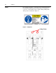
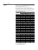
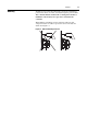
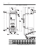
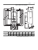
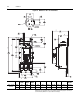
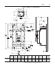
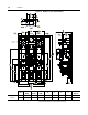
Figure 2.5 Dimensions: 201…251 A Controllers
All dimensions are approximate and are not intended for manufacturing purposes. Consult your
local Allen-Bradley distributor for complete dimension drawings.
Unit
A
Width
B
Height
C
Depth
DEFGHI
Approx.
Ship. Wt.
201…251 A
Controller
mm 225 560 253.8 150 504.1 157.25 91.189 44.311 79.811 30.4 kg
in. 8.858 22.047 9.992 5.906 19.847 6.2 3.59 1.74 3.14 67 lb.
157.25
(6.2)
6.4
(.250)
253.8
(9.992)
40.9
(1.6)
C
F
1.000
13.5
(.531)
50.8
(2.0)
24.9
(.980)
25
(.984)
48
(1.890)
DETAIL
AA
SCALE
#8-32 UNC-2B
M10 X 1.5
560
(22.047)
225
(8.858)
504.1
(19.847)
150
(5.906)
Ø
13
Ø
(.513)
Ø
11.5
Ø
(.453)
Ø
27.5
Ø
(1.083)
19.7
(.776)
91.189
(3.59)
164.126
(6.46)
152.749
(6.01)
44.311
(1.74)
79.811
(3.14)
245.689
(9.67)
80
(3.15)
SEE DETAIL AA
B
A
H
I
E
D
G