
User Manual User Manual

Wiring 3-19
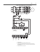
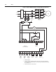
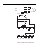
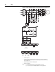
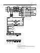
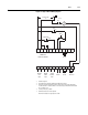
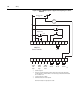
Figure 3.17 Typical Wiring Diagram for Shunt Trip Applications
➀
Customer supplied.
➁ Refer to the controller nameplate to verify the rating of the control power input voltage.
For units rated 625…1250 A, terminals 11 & 12 are factory pre-wired from terminal block
CP1 - terminals 1 & 4.
➂ Aux #2 should be set to fault operation.
11 12
13
14
15 16
17
18 19 20
21
23
24
25 26
27
28 29
30 31 32 33
22
34
L1/1
L3/5
L2/3
T3/6
T2/4
T1/2
M
3-Phase
Input Power
Branch
Protection
SMC-Flex
Controller
Aux #3Aux #2
Aux #4
Aux #1
SMC-Flex
Control Terminals
Start
Stop
ST
PTC
Input
TACH
Input
Ground
Fault
➀
➀
➀
➀
➀
➀
➀
➀
➂
➁