
User Manual User Manual

3-22 Wiring
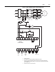
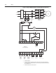
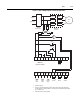
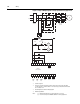
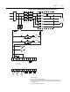
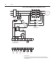
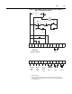
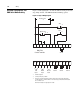
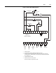
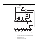
Figure 3.20 Typical Wiring Diagram for SMC-Off-Bypass Control
➀
Customer supplied.
➁ Refer to the controller nameplate to verify the rating of the control power input voltage.
For units rated 625…1250 A, terminals 11 & 12 are factory pre-wired from terminal block
CP1 - terminals 1 & 4.
11 12
13
14
15 16
17
18 19 20
21
23
24
25 26
27
28 29
30 31 32 33
22
34
L1/1
L3/5
L2/3
T3/6
T2/4
T1/2
M
3-Phase
Input Power
Branch
Protection
SMC-Flex
Controller
Aux #3Aux #2
Aux #4
Aux #1
SMC-Flex
Control Terminals
PTC
Input
TACH
Input
Ground
Fault
Bypass
Connector (BC)
BC
Start
Stop
OffSMC
Bypass
X
X
OL
➀
Bypass
➀
➀
➀
➀
➀
➀
➀
➀
➀
➁