DeviceNet™ Medium Voltage CONTROLLERS INSTALLATION MANUAL Bulletin 1500/1900
Important User Information Read this document and the documents listed in the Additional Resources section about installation, configuration, and operation of this equipment before you install, configure, operate, or maintain this product. Users are required to familiarize themselves with installation and wiring instructions in addition to requirements of all applicable codes, laws, and standards.
Table of Contents Chapter 1 DeviceNet Medium Voltage Controller Overview .......................... 1-1 Chapter 2 Designing Cable Systems ............................................................... 2-1 Medium Voltage Controller Cable System Construction ..................... 2-2 Chapter 3 DeviceNet Cable System Layout for Medium Voltage Controller Structures ......................................................................................... 3-1 Terminating Resistors .........................
Chapter 1 DeviceNet Medium Voltage Controller Overview This document describes the cable system construction and components associated with a DeviceNet™ network that is factory installed in Bulletin 1500/1900 CENTERLINE® and IntelliCENTER® Medium Voltage (MV) controllers. Refer to other documentation provided with the MV controller for general information on the installation, use and maintenance of this equipment.
1-2 DeviceNet Medium Voltage Controller Overview 1500-IN057C-EN-P – June 2013
Chapter 2 Designing Cable Systems When designing DeviceNet systems, it is necessary to consider the following (refer to publication DNET-UM072_-EN-P for additional requirements): Number of nodes does not exceed 64, with three nodes reserved for scanner (node 00), PC (node 62), and new device (node 63).
2-2 Designing Cable Systems Medium Voltage Controller Cable System Construction Do not apply high voltage to any installed DeviceNet cable system or its connectors. The high voltage will destroy internal capacitors in the connectors.
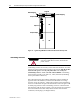
Chapter 3 DeviceNet Cable System Layout for Medium Voltage Controller Structures The DeviceNet trunk line assembly is mounted in a 6 inch by 6 inch low voltage wireway, which is mounted on the top of the main structure. (Refer to Figure 3.1). NOTE It may be necessary to remove the low voltage wireway, to prepare the structure for shipment.
3-2 DeviceNet Cable System Layout for Medium Voltage Controller Structures Trunk Line Male Linking Plug Female Linking Plug Drop Line Jumper Drop Line LV MV LV MV Drop Line Jumper Figure 3.1 – Typical 2-High MV Section with DeviceNet Trunk and Drop Lines. Terminating Resistors ATTENTION Before performing any service or maintenance activities on MV MCC sections, disconnect all power sources.
DeviceNet Cable System Layout for Medium Voltage Controller Structures Figure 3.2A – Left Termination Resistor 3-3 Figure 3.2B – Right Termination Resistor Terminating resistor (part number 1485A-C2) BLACK BLUE RED WHITE No Shield or bare wire required in class 1 DeviceNet MCCs Five-terminal plug connector Part # 22186-084-01 with jack screws (Left Side) Part #22105-006-012 with jack screws (Right Side) Figure 3.
3-4 DeviceNet Cable System Layout for Medium Voltage Controller Structures When the leftmost section is one end of trunk line, install the terminating resister in the leftmost connector. This end requires a female connector. When the rightmost section is one end of trunk line, install the terminating resister in the rightmost chetmag. This end requires a male connector. LV MV LV MV Figure 3.
Chapter 4 Linking DeviceNet Communication Cables in Medium Voltage Controllers Figure 4.1 – Joining the DeviceNet Trunk Line in Adjacent MV Sections Connecting DeviceNet within MV Controller Line-up General This section describes the recommended procedure for connecting DeviceNet communication cables (trunk lines) in MV controllers. The number of and type of sections shown above is arbitrary and for illustration purposes only. Drawings are not to scale.
4-2 Linking DeviceNet Communication Cables in Medium Voltage Controllers 3. When joining new sections to an existing MV MCC, remove the terminating resistor from the original end section (the one to which new sections were just joined). Install the terminating resistor according to the information supplied in the section ― Terminating Resistors‖ and ― Installing Terminating resistors‖ . 4. When new sections are added, always do the following design calculations: Check the total number of nodes.
Linking DeviceNet Communication Cables in Medium Voltage Controllers 4-3 1. Determine the safest and most convenient place to access the DeviceNet cable terminating point in the remote equipment. Drill the necessary cabinet or cover plate opening. Terminate the DeviceNet cable at the MV controller line-up in the LV wireway using the chetmag at the rightmost section or at the leftmost section.
4-4 Linking DeviceNet Communication Cables in Medium Voltage Controllers Re-location of Termination Resistors General If any MV controller units are relocated such that the termination resisters are no longer at the end of the trunk line, then they must be removed and re-installed at the end of the lineup. A unit that is added to either end of the lineup must also have the termination resister relocated from the existing end unit to the added unit.
Chapter 5 Typical DeviceNet Scanner Examples The following examples illustrate typical DeviceNet networks, including both the MV controller line-up and DeviceNet Scanner(s). The appropriate location for terminating resistors is shown for reference. 121Ohms DeviceNet Scanner LV MV LV MV LV MV LV MV LV MV LV MV LV MV LV MV You must attach a terminating resistor of 121 ohms, 1%, 1/4W or larger, to each end of the trunk line.
5-2 Typical DeviceNet Scanner Examples 121Ohms DeviceNet Scanner 121 Ohms 121 Ohms DeviceNet Scanner 121Ohms LV MV LV MV LV MV LV MV LV MV LV MV You must attach a terminating resistor of 121 ohms, 1%, 1/4W or larger, to each end of the trunk line. You must connect these resistors directly across the blue and white wires of the DeviceNet cable. Figure 5.
Typical DeviceNet Scanner Examples I MPORTANT 5-3 To minimize the impact of DeviceNet trunk length limitations, it is recommended that each MCC have an independent DeviceNet network. Accordingly, the following architecture shown must be used with caution. DeviceNet Scanner 121 Ohms 121Ohms LV MV LV MV LV MV LV MV LV MV LV MV LV MV LV MV Figure 5.
5-4 Typical DeviceNet Scanner Examples 1500-IN057C-EN-P – June 2013
Chapter 6 DeviceNet Power Supply I MPORT ANT The DeviceNet cable system requires a 24Vdc power source to operate. The power supply must: • Meet NEC Class 1 requirements as outlined in Article 725 • Be DeviceNet compatible as specified in the ODVA requirements Power supplies that do not satisfy both points listed above can result in damage to the DeviceNet signal and components, as well as failure to comply with NEC, local codes, and inspection.
6-2 DeviceNet Power Supply Note: Optional equipment is also shown. Figure 6.1 – LV Panel of Incomer with DeviceNet Power Supply Network Grounding at the Power Supply The DeviceNet cable must be grounded at only one location. The ideal choice is at the power supply. Ground the power supply and 24 Vdc common (black wire).
DeviceNet Power Supply 6-3 Connecting Two Power Supplies When an additional 24 Vdc Class 1 power supply must be installed for MV controller line-ups, the red trunk conductor between the power supplies must be broken. Locate a linking connector between sections and disconnect the red conductor (refer to the following figure). Ground only ONE of the two power supplies. break Red V+ White CAN_H Blue CAN_L Black V- (common) Power Supply Power Supply Figure 6.
6-4 DeviceNet Power Supply 1500-IN057C-EN-P – June 2013
Chapter 7 System Commissioning and Software Installation DeviceNet Tool Box The following optional items are suggested for IntelliCENTER and DeviceNet MV controller installation and maintenance: Hand tools—high-quality small-tip screwdriver, side-cutter, needlenose pliers, wire stripper Terminating resistors equal to 121 ohms 1%, 1/4W, metal film – part number 1485A-C2 Five-terminal plug (part number PN 942154-05 with jack screws; PN 942153-05 without jack scre
7-2 System Commissioning and Software Installation System Commissioning Checklist When installing a DeviceNet MV controller line-up, use the following checklist before applying power to the network: DeviceNet Software Installation checklist Number of nodes does not exceed 64, with three nodes reserved for scanner (node 00), PC (node 62), and new device (node 63) Individual drop lengths do not exceed 20 feet (6 m) Cumulative drop length does not exceed the desired network baud ra
System Commissioning and Software Installation 7-3 5. Use RSNetworx for DeviceNet to program and configure devices (e.g., full load current, acceleration rate, etc.). Do not download to a device before uploading from that device. Otherwise, the node and baud rates will be overwritten, requiring each device to be individually manually reprogrammed. Make sure to set communication-loss behavior for each device.
7-4 System Commissioning and Software Installation 1500-IN057C-EN-P – June 2013
Chapter 8 Filling a Prepared Space in a MV Controller Line-up with DeviceNet General Use this section when upgrading a Bulletin 1500 prepared space in a DeviceNet MV controller with a controller kit. Each DeviceNet component is factory wired within the controller kit and has a communication cable that plugs into the device on one end and the other end plugs into a DeviceNet port located on the flat vertical cable assembly mounted on the left side of the low voltage panel.
8-2 Filling a Prepared Space in a Medium Voltage Controller Line-up with DeviceNet Figure 8.1 – Prepared Space with “Bypass” Cable to Lower Panel 1500-IN057C-EN-P – June 2013 Figure 8.
Filling a Prepared Space in a Medium Voltage Controller Line-up with DeviceNet 8-3 Figure 8.3 – Typical Starter Kit LV Panel for DeviceNet (lower unit of 2-High) Procedure for Bottom Unit Note: This procedure does not require the top unit to be temporarily disconnected from DeviceNet. The prepared space does not have any DeviceNet connections or any DeviceNet wiring entering or crossing the unit.
8-4 Filling a Prepared Space in a Medium Voltage Controller Line-up with DeviceNet Software Update After installing a controller kit in an IntelliCENTER MV line-up, the user must update the IntelliCENTER software by following these directions. This is done by merging the data disks for the controller kit(s) with the existing IntelliCENTER database. Please refer to the IntelliCenter software manual 2100-UM002_-EN-P.
Appendix A How to Find Electronic Data Sheets (EDS) Background After installing IntelliCENTER software, an Electronic Data Sheet (EDS) file must be registered for each unique device in the MCC. This section details how to perform that task. Definition of EDS Files EDS files are simple text files used by network configuration tools— such as DeviceNetManager™, RSNetworx, and IntelliCENTER software—to help identify products and easily commission them on a network.
A-2 How to Find Electronic Data Sheets (EDS) Finding EDS Files for Other Devices 1500-IN057C-EN-P – June 2013 The program CD also contains a directory called EDS. This directory contains all EDS files sorted by the product family or classification. EDS files can be obtained at http://www.ab.com/networks/eds.
Medium Voltage Products, 135 Dundas Street, Cambridge, ON, N1R 5X1 Canada, Tel: (1) 519.740.4100, Fax: (1) 519.623.8930, www.ab.com/mvb Publication 1500-IN057C-EN-P – June2013 Supersedes Publication 1500-IN057B-EN-P – January 2007 Copyright © 2013 Rockwell Automation, Inc. All rights reserved. Printed in Canada.