DeviceNet™ Communication Module Catalog Number 160-DN2 Firmware 3.
Important User Information Solid state equipment has operational characteristics differing from those of electromechanical equipment. “Safety Guidelines for the Application, Installation and Maintenance of Solid State Controls” (Publication SGI-1.1 available from your local Rockwell Automation Sales Office or online at http://www.ab.com/manuals/gi) describes some important differences between solid state equipment and hard-wired electromechanical devices.
Summary of Changes The information below summarizes the changes made to this manual since its last release (March, 1999): Location Description of Changes Chapter 3 Added three new sections — Surge-Suppression, Common Mode Noise, and Output Disconnect — after the Low Voltage Directive 73/23/EEC Compliance section. Added EDS file search screen and removed obsolete Table 6 (EDS files for Bulletin 160 using a 160-DN2 version 3.000 or later).
S-2 Summary of Changes The March 1999 release of the Bulletin 160-DN2 DeviceNet Communication Module User Manual covers the software enhancements of Firmware Version 3.xxx and contains new and updated information. Bulletin 160-DN2 version 3.
Table of Contents Using This Manual Product Overview Quick Start for Experienced Users Installation and Wiring Preface Manual Objectives. . . . . . . . . . . . . . . . . . . . . . . . . . . . . . . . . . . . . . . . . . . . . . . . Who Should Use This Manual?. . . . . . . . . . . . . . . . . . . . . . . . . . . . . . . . . . . . . . Product References . . . . . . . . . . . . . . . . . . . . . . . . . . . . . . . . . . . . . . . . . . . . . . Conventions . . . . . . . . . . . . . . . . . . . . . . . . .
ii Table of Contents Modes of Operation DeviceNet Parameter Descriptions Using 160-DN2 with DeviceNet Scanner Publication 0160-5.18 - June 2003 Chapter 4 Powering Up the Drive . . . . . . . . . . . . . . . . . . . . . . . . . . . . . . . . . . . . . . . . . . . . Modes of Operation. . . . . . . . . . . . . . . . . . . . . . . . . . . . . . . . . . . . . . . . . . . . . . . Power-up Reset Mode. . . . . . . . . . . . . . . . . . . . . . . . . . . . . . . . . . . . . . . . . . . Run Mode . . . . . . . .
Table of Contents Troubleshooting Specifications DeviceNet Information iii Chapter 7 Understanding the COMM LED . . . . . . . . . . . . . . . . . . . . . . . . . . . . . . . . . . . . . 7-2 Understanding the FAULT LED . . . . . . . . . . . . . . . . . . . . . . . . . . . . . . . . . . . . . 7-3 Appendix A Electrical . . . . . . . . . . . . . . . . . . . . . . . . . . . . . . . . . . . . . . . . . . . . . . . . . . . . . Environmental . . . . . . . . . . . . . . . . . . . . . . . . . . . . . . . . . . .
iv Table of Contents Publication 0160-5.
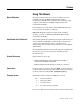
Preface Using This Manual Manual Objectives The purpose of this manual is to provide you with the necessary information to apply the Bulletin 160 SSC DeviceNet Communication Module. This manual describes methods to install, configure, and troubleshoot the Bulletin 160 SSC DeviceNet Communication Module. For information on specific features of the Bulletin 160 SSC drive, refer to the Bulletin 160 SSC User Manual.
P-2 Using This Manual Related Documentation For: Refer to: Publication Bulletin 160 SSC Drive User Manual Series A User Manual Series B User Manual Series C 0160-5.0 0160-5.9 0160-5.15 RSNetWorx for DeviceNet Software RSNetWorx for DeviceNet Getting Results Guide Online help (installed with the software) 9398-DNETGR ControlLogix ControlLogix User Manual 1756-6.5.13 SLC 500 and 1747-SDN DeviceNet Scanner Module Installation Instructions 1747-5.
Using This Manual Safety Precautions P-3 Please read the following safety precautions carefully: ! ! ! ! ! ATTENTION: Risk of injury or death exists. The drive contains high voltage capacitors which take time to discharge after removal of mains supply. Before installing or removing the DeviceNet Communication Module, make sure to isolate the mains supply from line inputs [L1, L2, L3 (R, S, T)]. Wait three minutes for capacitors to discharge to safe voltage levels.
P-4 Using This Manual DeviceNet Compatibility The 160-DN2 Communication Module is intended for use only with Bulletin 160 SSC Series A, Bulletin 160 SSC Series B, and Bulletin 160 SSC Series C (FRN 7.03 and later) devices. Bulletin 160 SSC (Series C) devices must use a 160-DN2 Communication Module to connect to a DeviceNet network. Bulletin 160 SSC (Series A and B) devices can use either a 160-DN2 or 160-DN1 Communication Module to connect to a DeviceNet network.
Chapter 1 Product Overview This chapter contains the following information: • physical layout of the module • location of configuration switches • DeviceNet overview and components Module Description The Bulletin 160 SSC DeviceNet Communication Module is an optional interface device designed to provide a direct, digital link between DeviceNet devices and the Bulletin 160 SSC drive. The module connects to the Bulletin 160 SSC through the expansion/ keypad port on the front of the drive.
1-2 Product Overview DIP Switches Figure 1.2 Module Rear View The Communication Module has one eight position DIP switch for setting the DeviceNet Node Address and Baud Rate. DIP switches are located on the rear of the module and are only accessible when the module is removed from the Bulletin 160 SSC drive. Expansion/Keypad Port Connector SW.7 - SW.8 = Baud Rate Selection (see page 3-7) Label with DeviceNet Serial Number Publication 0160-5.18 - June 2003 SW.1 - SW.
Chapter 2 Quick Start for Experienced Users Introduction This chapter can help you start using the Bulletin 160 DeviceNet Communication module. If you have previously installed or configured a DeviceNet network and are familiar with Rockwell Automation DeviceNet modules and drives, this information can help reduce installation and startup time. If you are uncertain, use the full installation/configuring information beginning in Chapter 3.
2-2 Quick Start for Experienced Users Procedures Step Refer to . . . 1 Review Attention statements in the Preface. Preface 2 Check the contents of the shipping box. Unpack the shipping box, making sure that it contains: — • Bulletin 160 DeviceNet module (Catalog Number 160-DN2) • 10-pin linear plug with probe holes and jack screws • DeviceNet Communication Module 160-DN2 User Manual If the contents are incomplete, call your local Allen-Bradley representative for assistance. Publication 0160-5.
Chapter 3 Installation and Wiring This chapter contains information necessary to: • Meet requirements for CE compliance (EMC / Low Voltage directives). • Suppress transient EMI from “hard contact” load switching. • Reduce high frequency common mode noise current. • Properly connect/disconnect power to the motor. • Remove a preinstalled Program Keypad Module or Ready/Fault Indicating Panel. • Configure and install the Communication Module. • Wire the DeviceNet communication cables.
3-2 Installation and Wiring EMC Directive 89/336/EEC Compliance The 160-DN2 Communication Module complies with Electromagnetic Compatibility (EMC) Directive 89/336/EEC when conforming to these installation requirements: • Applying the essential requirements for a conforming EMC installation for the Bulletin 160 SSC drive. Refer to the Bulletin 160 SSC User Manual. • Connecting the DeviceNet cable shield to the SSC drive’s protective earth terminal, PE, with a low impedance connection.
Installation and Wiring 3-3 is 220 ohms and 0.50 microfarads. Select the voltage rating for the normal AC voltages. A typical surge suppressor that can be used for most transient EMI problems is Electrocube part number RG1676-16 (rated 480V ac). Surge suppressors are usually most effective when connected at the inductive loads.
3-4 Installation and Wiring Common Mode Noise To greatly reduce high frequency common mode noise current coupled to ground in high capacitance connections, connect a common mode choke at the drive end of the motor cable. The common mode choke reduces the rise time of the high frequency noise by a factor of 10-20, and the amplitude by a factor of 5. For multiple 460 volt drive installations with sensitive equipment (e.g. PLC’s, temperature sensors, sonar detectors, strain gauges, etc.
Installation and Wiring Removing Program Keypad Module or Ready/Fault Panel 3-5 Before installing the Communication Module, it may be necessary to remove a previously installed module such as a Program Keypad Module or Ready/Fault Indicating panel. ! ATTENTION: Risk of injury or death exists. The drive contains high voltage capacitors which take time to discharge after removal of mains supply.
3-6 Installation and Wiring Setting the DeviceNet Node Address DIP switches 6 through 1 set the module’s node address using binary addressing. The factory default setting is DeviceNet address 63. Figure 3.6 Setting the Node Address DeviceNet Address 000000 - 111111 (0 to 63) ON = 1 OFF = 0 1 2 3 4 5 6 7 8 N O To set the DeviceNet node address: 1. Refer to Table 3.A below for the switch settings of a specific address. 2.
Installation and Wiring Dip switches 7 and 8 set the baud rate at which the Communication Module communicates on the network. The factory default setting for baud rate is 125 kbps. Figure 3.7 Setting the Baud Rate 1 2 3 4 5 6 7 8 Setting the Baud Rate 3-7 N O Use DIP Switch 8 and 7 for setting the DeviceNet Baud Rate. ON = 1 OFF = 0 To set the DeviceNet Baud Rate: 1. Refer to Table 3.B for the switch setting of a specific Baud Rate. 2.
3-8 Installation and Wiring Installing the Communication Module After setting the DIP switches, secure the Communication Module to the drive by following these steps: 1. Insert the module, ensuring that the pins on the back of the module line up with the drive’s expansion port. 2. Press down on the module until it is fully seated. The module is fully seated when its sides are resting on the drive’s face. 3. Press down on the latch until it snaps into place. 10 11 Figure 3.
Installation and Wiring Wiring the DeviceNet Connector 3-9 Follow these recommendations for communications wiring: • See DeviceNet Cable System Planning and Installation Manual, Publication DN-6.7.2, for planning and installing DeviceNet networks. • Keep communication wiring away from high noise sources such as motor cables. • Increase noise immunity by: – Using a trunk line in place of a drop line. – Using a ferrite cable clamp around the communication line (see Figure 3.9).
3-10 Installation and Wiring Connecting the DeviceNet Drop Line to the Module To connect your module DeviceNet drop line: 1. Turn off the network power supply. ! ATTENTION: Do not wire the Communication Module with the network power supply on. Wiring the module with the network power supply on may short your network or disrupt communication. 2. Make sure that the DeviceNet 10-pin Linear Plug is correctly wired (see Figure 3.9). 3. Locate the DeviceNet connector on the bottom of the module. 4.
Chapter 4 Modes of Operation This chapter contains information about: • Powering up the drive with an installed 160-DN2 DeviceNet communication module. • Understanding the module’s modes of operation. Before you apply power, review the Safety Precautions on Preface page P-3. Powering Up the Drive After you have installed the 160-DN2 module, apply power to the drive and to the Network. The COMM LED should flash green or turn solid green. If it does not, refer to Chapter 7, Troubleshooting.
4-2 Modes of Operation Modes of Operation (Continued) Power-up Reset Mode (Continued) If the power up or reset sequence fails, the COMM LED will turn solid red and the 160-DN2 module will enter the Error mode (see heading below for more information). Table 4.A COMM LED State During Power-up Reset Mode COMM LED State Description Flashes Green 1/4 second, Occurs when power is applied to module. Red 1/4 second, then goes blank Blank Solid Red Solid Green Power-up initialization is taking place.
Chapter 5 DeviceNet Parameter Descriptions This chapter contains: • a description of DeviceNet parameters • the definition of Electronic Data Sheet (EDS) files • Bulletin 160 SSC Interface parameters • brief description of Bulletin 160 parameters Important: This chapter describes the parameter set for a Series C Bulletin 160. If you are using a Series A or Series B Bulletin 160, not all the parameters listed in this manual may apply to that drive.
5-2 DeviceNet Parameter Descriptions Parameters and EDS File (Continued) Parameter values may be read or written via DeviceNet. Writing a value to a parameter may configure drive operations such as acceleration or deceleration rates. Writing a value to a parameter may also configure DeviceNet operations such as which input or output assemblies are to be used for polled I/O communications with a master. Reading a parameter value gives you status information.
DeviceNet Parameter Descriptions Bulletin 160 SSC Interface Parameters 5-3 The Bulletin 160 SSC Interface parameters are grouped together logically. The following sections provide information about the Bulletin 160 SSC Interface parameter groups: • DeviceNet Parameters • Drive Display Parameters • Drive Program Parameters The following parameter lists summarize the Bulletin 160 SSC Interface.
5-4 DeviceNet Parameter Descriptions DeviceNet Parameters (Continued) Parameter Number Name and Description Object Mapping (Class-InstanceAttribute) Min./Max. Range Factory Default 106 [Bus Off Count] 0x03-1-4 This read/write parameter counts the number of times the CAN chip went to the bus off state. This counter stops counting when the count reaches 255. Any write to this parameter will reset the counter to 0.
DeviceNet Parameter Descriptions 5-5 DeviceNet Parameters (Continued) Parameter Number Name and Description Object Mapping (Class-InstanceAttribute) Min./Max. Range Factory Default 110 0xB4-1-8 [Assembly Word 1] This read/write parameter is used when P108 - [Input Assembly] is set to 102 Custom Parameter Based Assembly. It defines the second word in an assembly built from Bulletin 160 parameters. A 0 value defines the end of the assembly. For more information, see Appendix B, page B-27.
5-6 DeviceNet Parameter Descriptions Drive Display Parameters (Read Only) Parameter Number 01 02 03 04 05 06 07 08 09 Parameter Name [Output Frequency] [Output Voltage] [Output Current] [Output Power] [Bus Voltage] [Cmd Frequency] [Present Fault] [Heatsink Temp] [Drive Status] Below is a brief description of the Bulletin 160 SSC Interface Display Group parameters. Refer to the Bulletin 160 SSC User Manual for more detailed information on these parameters.
DeviceNet Parameter Descriptions 5-7 Drive Display Parameters (Read Only) (Continued) Parameter Number 15 Parameter Name [Preset Status] Object Mapping (Class-InstanceAttribute) 0xB3-1-15 Description Units Open (0) and closed (1) state of TB3 inputs SW1, SW2, and SW3. Binary Number Bit 3 Bit 2 Bit 1 Bit 0 SW1 SW2 SW3 Unused 16 17 18 19 [Analog Input] [Fault Buffer 0] [Fault Buffer 1] [Fault Buffer 2] 0xB3-1-16 0xB3-1-17 0xB3-1-18 0xB3-1-19 The analog input as a percent of full scale.
5-8 DeviceNet Parameter Descriptions Drive Program Parameters Parameter Number Parameter Name Below is a brief description of the Bulletin 160 SSC Interface Program Group parameters. Refer to the Bulletin 160 SSC User Manual for more detailed information on these parameters. Object Mapping (Class-InstanceAttribute) Description Units 30 [Accel Time 1] 0xB3-1-30 Time to ramp from 0 Hz to maximum frequency. 0.1 Seconds 31 [Decel Time 1] 0xB3-1-31 Time to ramp from maximum frequency to 0 Hz. 0.
DeviceNet Parameter Descriptions 5-9 Drive Program Parameters (Continued) Parameter Number Parameter Name Object Mapping (Class-InstanceAttribute) Description Units 54 [Clear Fault] 0xB3-1-54 Setting to 1 performs a fault reset. Numeric Value 55 [Probe Address] 0xB3-1-55 Used by Allen-Bradley service personnel. Numeric Value 56 [Reset Functions] 0xB3-1-56 Sets all parameters to their factory default. Numeric Value 57 [Program Lock] 0xB3-1-57 Locks all program group parameters.
5-10 DeviceNet Parameter Descriptions Drive Program Parameters (Continued) Parameter Number 80 Parameter Name [Stall Disable] Object Mapping (Class-InstanceAttribute) 0xB3-1-80 Description Amount of time that the drive must be in a stall condition before it causes a stall fault. ! Units Numeric Value ATTENTION: Risk of equipment damage exists. Continuous operation at high currents caused by a stall can cause motor damage. 81 [Proc Kp Gain] 0xB3-1-81 Proportional gain used by the PI regulator.
Chapter 6 Using 160-DN2 with DeviceNet Scanner This chapter provides an overview of how to use the Bulletin 160DN2 Communication Module with a DeviceNet Scanner. Scanners act as “Masters” on a DeviceNet Network for the I/O communication with a 160-DN2 module. Scanners periodically send I/O messages to a 160-DN2 module at a set frequency, and the module responds to these I/O messages by sending status messages back to the scanner.
6-2 Using 160-DN2 with DeviceNet Scanner Needed Tools The following tools are needed to set up the 160-DN2 module on a DeviceNet network and operate with a scanner: • • • RSLinx Software (version 2.3x or higher) RSNetWorx for DeviceNet (version 3.xxx of higher) RSLogix Programming Software Setting Device MAC ID’s Every device on a DeviceNet network must have a unique MAC ID between 0 and 63. Use the network and a configuration tool such as RSNetWorx for DeviceNet to set the MAC ID on the scanner.
Using 160-DN2 with DeviceNet Scanner Using RSNetWorx for DeviceNet (Continued) 6-3 Creating an EDS File If the 160-DN2 communication module and Bulletin 160 SSC drive appear as an unrecognized device, create an EDS file for it. 1. Right-click the “Unrecognized Device” icon, and select Register Device in the menu. The EDS Wizard (Figure 6.2) appears. 2. Click Next to display the next step. 3. Select Upload EDS, and then click Next. 4. Type a description (if desired), and then click Next. 5.
6-4 Using 160-DN2 with DeviceNet Scanner Using RSNetWorx for DeviceNet (Continued) Accessing and Editing Parameters Parameters in the drive and 160-DN2 module can be edited with RSNetWorx for DeviceNet. 1. After creating an EDS file, right-click on the icon for the Bulletin 160 SSC drive and 160-DN2 module and select Properties. The Bulletin 160 Drive dialog box appears. 2. Click the Parameters tab (Figure 6.3).
Using 160-DN2 with DeviceNet Scanner Selecting Input and Output Assemblies for I/O Messaging 6-5 The DeviceNet Specification defines Assembly Objects as objects that “bind attributes of multiple objects to allow data to or from each object to be sent over a single connection.” The 160-DN2 module uses Assembly Objects to send data to and from a Scanner over an I/O connection. The terms input and output are defined from the scanner’s point of view.
6-6 Using 160-DN2 with DeviceNet Scanner Selecting Input and Output Assemblies for I/O Messaging (Continued) An example screen (Figure 6.4) shows Output Assembly 103 and Input Assembly 104 selected. The following steps were used: Changing the Output Assembly 1. In the Current Value column, double-click on the value for Parameter 107 - [Output Assembly]. 2. Enter Assembly Number “103.” 3. Click Apply to save the changes. Changing the Input Assembly 1.
Using 160-DN2 with DeviceNet Scanner Enabling Network Control 6-7 The 160-DN2 module must be configured to accept commands from the network. To do this, configure the drive “Input Mode” parameter (Figure 6.5). Configuring Drive Input Mode 1. In the Current Value column, click on the value for Parameter 46 - [Input Mode] and select “Network Control” from the dropdown list. Important: Remember to jumper or close drive Terminals 7 and 8 on TB2 before the drive can start. 2. Click Apply to save the changes.
6-8 Using 160-DN2 with DeviceNet Scanner Enabling Network Control (Continued) For the new input mode to take effect, modify the drive “Reset Functions” parameter (Figure 6.6). Modifying Drive Reset Functions 1. In the Current Value column, click on the value for P56 - [Reset Functions] and select “Reset Input Mode” from the dropdown list. 2. Click Apply to save the changes. Figure 6.6 Reset Input Mode Screen Publication 0160-5.
Using 160-DN2 with DeviceNet Scanner Configuring the 160 to Accept Speed Commands from the Network 6-9 The 160-DN2 module must be configured to accept its speed commands from the network. To do this, change the drive “Frequency Select” parameter (Figure 6.7). 1. In the Current Value column, click on the value for P59 [Frequency Select] and select “Internal Freq” from the dropdown list. 2. Click Apply to save the changes. 3. Click OK to close the window. Figure 6.
6-10 Using 160-DN2 with DeviceNet Scanner Configuring the Scanner The scanner must be configured to communicate with the 160-DN2 module and connected Bulletin 160-SSC drive. Example Network After the module is configured, the connected drive and module become a single node on the network. This section provides a step-bystep procedure to configure the scanner in a network, such as the simple network example shown in Figure 6.8.
Using 160-DN2 with DeviceNet Scanner Configuring the Scanner (Continued) 6-11 Setting Up the Scan List For the scanner to communicate with a drive, the scanner must be configured and the drive’s node number must be added to its scan list. 1. Go online with RSNetWorx for DeviceNet. The devices on the network are displayed in the configuration view. Figure 6.9 Configuration View (Graph) 2. Right-click the DeviceNet scanner (MAC ID 00 in Figure 6.9) and select Properties.
6-12 Using 160-DN2 with DeviceNet Scanner Configuring the Scanner (Continued) Figure 6.10 Scanlist Page in the Scanner Module Dialog Box 7. In the “Scanlist,” select the drive, and then click Edit I/O Parameters. The Edit I/O Parameters dialog box (Figure 6.11) appears. Figure 6.11 Edit I/O Parameters Dialog Box 8. Select the type(s) of data exchange (Strobed, Polled, Change of State or Cyclic). In our example, we selected Polled. Publication 0160-5.
Using 160-DN2 with DeviceNet Scanner Configuring the Scanner (Continued) 6-13 9. Type the number of bytes that are required for your I/O in the Input Size and Output Size boxes. Refer to Appendix B, pages B-23 to B-28 for all Bulletin 160 Assemblies. In our example, we typed “4” in the Input Size and Output Size boxes because we are using Output Assembly 21 and Input Assembly 71. 10. Set the required rate for the data exchange selected in step 8. (Click Help for more information.
6-14 Using 160-DN2 with DeviceNet Scanner Configuring the Scanner (Continued) Figure 6.12 Input Page on the Scanner Module Dialog Box If you selected the Automap on Add box in the Scanlist tab (Figure 6.10), RSNetWorx has already mapped the I/O. If it is not mapped, click Automap to map it. If you need to change the mapping, click Advanced and change the settings. Click Help for assistance. 2. In the Memory box, select a location in scanner memory.
Using 160-DN2 with DeviceNet Scanner Configuring the Scanner (Continued) 6-15 Mapping the Output I/O 1. In the Scanner Module dialog box, click the Output tab. To display this dialog box, right-click the scanner in the configuration view (Figure 6.9). Figure 6.13 Output Page on the Scanner Module Dialog Box If you selected the Automap on Add box in the Scanlist tab (Figure 6.10), RSNetWorx has already mapped the I/O. If it is not mapped, click Automap to map it.
6-16 Using 160-DN2 with DeviceNet Scanner Configuring the Scanner (Continued) 3. In the Start DWord box, select the word in memory at which the data should start. In our example, we selected 0. Due to the 32-bit data used by the 1756-DNB scanner in our example, the Logic Command and Speed Reference information are combined in address 1:O.Data[0], where 1 equals the slot number of the scanner.
Using 160-DN2 with DeviceNet Scanner Using I/O Messaging (Continued) 6-17 ControlLogix Example Table 6.C Tags for the Example Program Tag Name Local:1:I Local:1:O DriveCommandClearFault DriveCommandJog DriveCommandStart DriveCommandStop Type DINT[] DINT[] BOOL BOOL BOOL BOOL Tag Name DriveFeedback DriveInputImage DriveOutputImage DriveReference DriveStatusFaulted DriveStatusRunning Type INT INT[2] INT[2] INT BOOL BOOL Figure 6.
6-18 Using 160-DN2 with DeviceNet Scanner Using I/O Messaging (Continued) Figure 6.14 Example ControlLogix Ladder Logic Program (Continued) DriveCommandClearFault DriveOutputImage[0].3 8 This rung transfers the reference tag to the drive’s output image. 9 This rung copies the output image into the 32-bit DeviceNet scanner output structure. The length in this instruction is one because only one 32-bit array element of the destination is used. 10 (End) Publication 0160-5.
Using 160-DN2 with DeviceNet Scanner Using I/O Messaging (Continued) 6-19 PLC-5 Example Table 6.D Control File for Block Transfer EN ST DN ER CO EW NR TO RW RLEN BT20:0 BT20:1 0 0 0 0 0 0 0 0 0 0 0 0 0 0 0 0 0 0 62 62 DLEN 0 0 FILE 9 10 ELEM R 0 0 00 00 G 0 0 S 0 0 Figure 6.15 Example PLC-5 Ladder Logic Program The scanner gathers drive status data via the DeviceNet network.
6-20 Using 160-DN2 with DeviceNet Scanner Using I/O Messaging (Continued) Figure 6.
Using 160-DN2 with DeviceNet Scanner Using I/O Messaging (Continued) 6-21 SLC Example Figure 6.16 Example SLC Ladder Logic Program The scanner gathers drive status data via the DeviceNet network. The M-File is copied into the N9 data file in the SLC to move the drive status information to a convenient location. CO P Copy File Source Dest Length 0000 Bulletin 160 RUNNING Status Bit N9:0 #M1:1:0 #N9:0 128 Operator Display Drive Running Status Bit O:3.
6-22 Using 160-DN2 with DeviceNet Scanner Using I/O Messaging (Continued) Figure 6.16 Example SLC Ladder Logic Program (Continued) 0007 Bulletin 160 CLEAR FAULTS Command Bit N10:0 Operator Input Drive Clear Faults Command Bit I:2.0 3 1746-I*16 0008 3 Bulletin 160 REFERENCE Command Word MOV Move Source Dest This rung enables the scanner. It changes the scanner to RUN mode. N21:0 0< N10:1 0< 1747-SDN Scanner Enable Bit O:1.
Using 160-DN2 with DeviceNet Scanner Using Explicit Messaging 6-23 This section provides information and examples that explain how to use Explicit Messaging to monitor and configure the 160-DN2 module and connected Bulletin 160-SSC drive. ! ! ATTENTION: Hazard of injury or equipment damage exists. The examples in this publication are intended solely for purposes of example. There are many variables and requirements with any application.
6-24 Using 160-DN2 with DeviceNet Scanner Using Explicit Messaging (Continued) Figure 6.17 ControlLogix Message Format in RSLogix 5000 ➊ ➐ ➋ ➌ ➎ ➍ ➏ ➑ ➒ ➓ See Page 6-25 for a description of the data required for each box (1 – 7). TIP: To display the Message Configuration dialog box in RSLogix 5000, add a message instruction, create a tag for the message (properties: base tag, MESSAGE data type, controller scope), and click the blue box inside the message. Publication 0160-5.
Using 160-DN2 with DeviceNet Scanner Using Explicit Messaging (Continued) 6-25 The following table identifies the number of Explicit Messages that can be executed at a time. Messages at One Time Scanner 1756-DNB 5 Refer To Figure 6.17 ControlLogix Message Requests and Responses Box ➊ ➋ ➌ ➍ ➎ ➏ ➐ ➑ ➒ ➓ Description Message Type The message type must be CIP Generic. Service Type This box contains the type of function that the message will perform. The default function is Custom.
6-26 Using 160-DN2 with DeviceNet Scanner Using Explicit Messaging (Continued) Explicit Messages for a PLC-5 or SLC Controller Transaction blocks in PLC-5 and SLC scanners accommodate both downloading Explicit Message Requests and uploading Explicit Message Responses. The scanner module can accommodate one request or response for each transaction block. Each transaction block must be formatted as shown in Figure 6.18 or Figure 6.19. Figure 6.
Using 160-DN2 with DeviceNet Scanner Using Explicit Messaging (Continued) 6-27 PLC-5 / SLC Explicit Message Requests Word 0 1 2 3 4 5 6 – 31 Description Command (Least Significant Byte) The Command is a code that instructs the scanner how to administer the request during each download.
6-28 Using 160-DN2 with DeviceNet Scanner Using Explicit Messaging (Continued) PLC-5 / SLC Explicit Message Responses Word 0 1 2 3 – 31 Description Status (Least Significant Byte) One of the following status codes is provided during each upload: 00 = Ignore transaction block (empty) 01 = Transaction completed successfully 02 = Transaction in progress (not ready) 03 = Slave not in scan list 04 = Slave offline 05 = DeviceNet port disabled or offline 06 = Transaction TXID unknown 08 = Invalid command co
Using 160-DN2 with DeviceNet Scanner Using Explicit Messaging (Continued) 6-29 Executing Explicit Messages There are five basic events in the Explicit Messaging process. The details of each step will vary depending on the controller (ControlLogix, PLC-5, or SLC). Refer to the documentation for your controller. Important: There must be a request message and an response message for all Explicit Messages, whether you are reading or writing data. Figure 6.
6-30 Using 160-DN2 with DeviceNet Scanner Using Explicit Messaging (Continued) ControlLogix Example Data Format for a Read and Write Parameter The data in this example is for a Bulletin 160-SSC drive at MAC ID 1. For a description of the content in each box, refer to the “Formatting Explicit Messages” subsection starting on Page 6-23. Figure 6.21 ParameterReadMessage Screen Publication 0160-5.
Using 160-DN2 with DeviceNet Scanner Using Explicit Messaging (Continued) 6-31 Figure 6.22 ParameterWriteMessage Screen Box Setting Description Message Type Service Type Class Instance Attribute Source Element Source Length CIP Generic Set Attribute Single B3 (hex) 1 (dec) 1E (hex) Must be CIP Generic Defines Service Code as text message 160 Parameter Table Object Number of Instances Parameter Number ➀ User-created tag for parameter data Data Type ➁ 2 (bytes) Refer to . . .
6-32 Using 160-DN2 with DeviceNet Scanner Using Explicit Messaging (Continued) Table 6.E Tags for ControlLogix Example Explicit Messaging Program Tag Names for Read Messages StartParameterRead Output_Current ParameterReadMessage Type BOOL INT MESSAGE Tag Names for Write Messages StartParameterWrite ParameterWriteMessage Accel_Time_1 Type BOOL MESSAGE INT Figure 6.23 ControlLogix Example Explicit Messaging Ladder Logic Program This rung reads the value of parameter 3 - [Output Current].
Using 160-DN2 with DeviceNet Scanner Using Explicit Messaging (Continued) 6-33 PLC-5 Example Data Format for a Read and Write Parameter The data in this example is for a Bulletin 160-SSC drive at MAC ID 1. For a description of the content of the data file, refer to the “Formatting Explicit Messages” subsection starting on Page 6-23. Request Data for Read of Drive Parameter 3 Address Value (hex) N30:0 N30:1 N30:2 0101 0006 0E01 N30:3 N30:4 N30:5 00B3 0001 0003 Description Refer to . . .
6-34 Using 160-DN2 with DeviceNet Scanner Using Explicit Messaging (Continued) Figure 6.24 PLC-5 Example Explicit Messaging Ladder Logic Program When I:000/17 is set to true, a one-time Block Transfer Write sends data to the scanner. The Move instruction then initializes the first word of the data file that is used by the Block Transfer Read instruction in the next rung.
Using 160-DN2 with DeviceNet Scanner Using Explicit Messaging (Continued) 6-35 SLC Example Data Format for a Read and Write Parameter The data in this example is for a Bulletin 160-SSC drive at MAC ID 1. For a description of the content of the data file, refer to the “Formatting Explicit Messages” subsection on Page 6-23. Request Data for Read of Drive Parameter 3 Address Value (hex) N20:10 N20:11 N20:12 0101 0006 0E01 N20:13 N20:14 N20:15 00B3 0001 0003 Description Refer to . . .
6-36 Using 160-DN2 with DeviceNet Scanner Using Explicit Messaging (Continued) Important: To originate a scanner transaction, use a copy operation to M0:[slot number]:224. Then, use a copy operation to read M1:1.224 for the result. If more than one message is enabled, use the TXID to determine which message you are reading. Figure 6.
Chapter 7 Troubleshooting This chapter provides information for troubleshooting potential problems with the 160-DN2 DeviceNet Communication Module and network. Figure 7.1 Module Front View READY LED - Green when drive is powered up. TMTM CONFORMANCE TESTED CONFORMANCE TESTED FAULT LED - Red when drive is faulted Off when drive not faulted. COMM LED - Bi-colored LED (red/green) provides status information on DeviceNet communications. The table below summarizes the operation of the LED.
7-2 Troubleshooting ! Understanding the COMM LED ATTENTION: Do not attempt to defeat or override fault circuits. The cause of a fault indication must be determined and corrected before attempting operation. Failure to correct a drive or system malfunction may result in personal injury and/or equipment damage due to uncontrolled machine system operation. The COMM LED provides status information on 160-DN2 module operations.
Troubleshooting Understanding the FAULT LED 7-3 When the FAULT LED is Red, a drive fault is present. To view the fault code, you must either view P7 - [Present Fault] or read the value of Class 0x29 (Control Supervisor Object) Instance 1 Attribute 13 (Fault Code). If you view P7 - [Present Fault], refer to Table 7.B for an explanation of each fault code. If you read the value of Attribute 13 (Fault Code), refer to Table 7.C. Table 7.
7-4 Troubleshooting Understanding the FAULT LED (Continued) Table 7.B Bulletin 160 SSC Interface Fault Codes (Continued) Fault Code Fault Indication 43 VW Short 46 48 50 51 52 Description Excessive current has been detected between these two drive output terminals. Intermittent Phase An external short occurred while running diagnostics. Fault Reprogramming Fault Occurs when reset defaults is performed. No DeviceNet Power 24 volt network power is not detected.
Troubleshooting 7-5 Understanding the FAULT LED (Continued) Table 7.C DeviceNet Fault Codes (Class 0x29, Instance 1, Attribute 13) (Continued) Fault Code (hex) Fault Indication 2342 UW Short Excessive current has been detected between these two drive output terminals. Check the motor and external wiring to the drive output terminals for a shorted condition. 2343 VW Short Excessive current has been detected between these two drive output terminals.
7-6 Troubleshooting Notes: Publication 0160-5.
Appendix A Specifications Electrical Network Supply Voltage 11 to 25V dc Node Current Consumption 40 mA maximum ➀ Power Consumption 1W maximum Environmental Ambient Temperature Operating Storage 0 to 50° C (32 to 122° F) -40 to 85° C (-40 to 185° F) Relative Humidity 0 to 95% non-condensing Vibration 1.0 G operational 2.5 G non-operational Shock 15.0 G operational 30.0 G non-operational Altitude 1,000 m (3,300 ft.
A-2 Specifications Notes: Publication 0160-5.
Appendix B DeviceNet Information The DeviceNet 160-DN2 module enables a Bulletin 160 SSC drive to operate as a slave device on a DeviceNet network. The module supports Explicit Messages and Polled or Change of State/Cyclic I/O Messages of the predefined master/slave connection set. A scanner must be used to properly route messages to a slave device. The 160DN2 module does not support the Explicit Unconnected Message Manager (UCMM).
B-2 DeviceNet Information Object Classes The 160-DN2 module supports these object classes: Class Supported Data Types Object Refer to . . .
DeviceNet Information Class Code 0x01 — Identity Object B-3 Class Attributes Attribute ID Access Rule Name Data Type Value 1 Get Revision UINT 1 2 Get Max Instances UINT 2 6 Get Max ID Class UINT 7 7 Get Max ID Instance UINT 7 Number of Instances: 2 Instance 1 Attributes: Drive Instance ➀ Attribute ID Access Rule Name Data Type Value 1 Get Vendor UINT 1 2 Get Product Type UINT 2 3 Get Product Code UINT — 4 Get Revision Major Revision Minor Revision Struc
B-4 DeviceNet Information Class Code 0x01— Identity Object (Continued) Instance 2 Attributes: DeviceNet Instance Attribute ID Access ID 1 Get Vendor UINT 1 2 Get Product Type UINT 105 = Subassembly 3 Get Product Code UINT 1 4 Get Revision Major Minor Structure of USINT USINT 3 1 5 Get Status WORD 0 = Not Owned 1 = Owned by Master 6 Get Serial Number UDINT Unique 32 bit number Get Product Name String Length ASCII String Structure of USINT STRING 16 “Bulletin 160 DN2” 7
DeviceNet Information B-5 Class Code 0x03 — DeviceNet Object Class Attributes: None Supported Number of Instances: 1 Instance 1 Attributes Attribute ID Access Rule Name Data Type Value 1 Get/Set Node Address USINT 0 to 63 2 Get/Set Data Rate USINT 0 to 2 3 Get/Set BOI BOOL 0 = Hold in error state on BOI error 1 = Reset CAN chip on BOI error 4 Get/Set Bus-off Counter USINT 0 to 255 5 Get Allocation Info Allocation Choice Master Node Addr Structure of: BYTE USINT 8 Get MAC I
B-6 DeviceNet Information Class Code 0x05 — Connection Object Class Attributes: None Supported Number of Instances: 3 Instance 1 Attributes: Explicit Message Instance Attribute ID Access Rule Name Data Type Value 1 Get State USINT 0 = Nonexistant 1 = Configuring 3 = Established 4 = Timed out 5 = Deferred delete 2 Get Instance Type USINT 0 = Explicit Message 3 Get Transport Class Trigger USINT 0x83 4 Get Produced Connection ID UINT 10xxxxxx100 where xxxxxx = Node address 5 Get
DeviceNet Information B-7 Class Code 0x05 — Connection Object (Continued) Instance 2 Attributes: Polled I/O Message Connection Attribute ID Access Rule 1 Get 2 3 Name Data Type Value 0 = Nonexistant 1 = Configuring 3 = Established 4 = Timed out State USINT Get Instance Type USINT 1 = I/O Message Get Transport Class Trigger USINT 0x82 4 Get Produced Connection ID UINT 10xxxxxx100 where xxxxxx = Node address 5 Get Consumed Connection ID UINT 10xxxxxx101 where xxxxxx = Node address
B-8 DeviceNet Information Class Code 0x05 — Connection Object (Continued) Instance 4 Attributes: Change of State/Cyclic Instance Attribute ID Access Rule 1 Get 2 3 Name Data Type Value 0 = Nonexistant 1 = Configuring 3 = Established 4 = Timed out State USINT Get Instance Type USINT 1 = I/O Message Get Transport Class Trigger USINT 0x82 4 Get Produced Connection ID UINT 10xxxxxx100 where xxxxxx = Node address 5 Get Consumed Connection ID UINT 10xxxxxx101 where xxxxxx = Node addre
DeviceNet Information Class Code 0x0F — Parameter Object B-9 Class Attributes Attribute ID Access Rule Name Data Type Value 1 Get Revision UINT 1 2 Get Max Instance UINT 118 8 Get Parameter Class Descriptor WORD 0x0B 9 Get Configuration Assembly Instance UINT 190 10 Get Native Language USINT 0 = English Number of Instances: 118 Instance 1 through 118 Attributes Attribute ID Access Rule 1 Set Parameter Value data type specified in Descriptor, Data Type and ➀ Data Size
B-10 DeviceNet Information Class Code 0x0F — Parameter Object (Continued) Instance 1 through 118 Attributes (Continued) ➀ Attribute ID Access Rule Name Data Type Value 18 Get Divisor Link UINT ➀ 19 Get Base Link UINT ➀ 20 Get Offset Link UINT ➀ 21 Get Decimal Precision USINT ➀ Value varies based on parameter instance. Common Services Publication 0160-5.
DeviceNet Information Class Code 0x10 — Parameter Group Object B-11 Class Attributes Attribute ID Access Rule Name Data Type Value 1 Get Revision UINT 1 2 Get Max Instance UINT 3 8 Get Native Language USINT 0 = English Number of Instances: 3 Instance 1 through 3 Attributes ➀ Attribute ID Access Rule Name Data Type Value 1 Get Group Name String SHORT_STRING ➀ 2 Get Number of members in group UINT ➀ 3 Get 1st Parameter Number in Group UINT ➀ 4 Get 2nd Parameter
B-12 DeviceNet Information Class Code 0x28 — Motor Data Object Class Attributes: None Supported Number of Instances: 1 Instance 1 Attributes Attribute ID Access Rule 6 Get/Set Rated Current UINT 0 to 100.00 0.
DeviceNet Information B-13 Class Code 0x29 — Control Supervisor Object Class Attributes: None Supported Number of Instances: 1 Instance 1 Attributes Attribute ID Access Rule 3 Get/Set RunFwd BOOL 0 to 1 0 See page B-15. 4 Get/Set RunRev BOOL 0 to 1 0 See page B-15. 5 Get/Set NetCtrl BOOL 0 to 1 0 See page B-15. Name Data Type Min/Max Default Description 3 = Ready 4 = Enabled 7 = Faulted (See Figure B.1 on page B-14.
B-14 DeviceNet Information Class Code 0x29 — Control Supervisor Object (Continued) Common Services Implemented for: Service Code Class Instance Service Name 0x0E No Yes Get_Attribute_Single 0x10 No Yes Set_Attribute_Single State Transition Diagram The following State Transition Diagram provides a graphical description of the states and state transitions that are described for attribute 6 on page B-13. Figure B.
DeviceNet Information Class Code 0x29 — Control Supervisor Object (Continued) B-15 Run/Stop Event Matrix Attribute 5, NetCtrl is used to request that Run/Stop events be controlled from the network. However, before Run/Stop control is accomplished from the network, these things must occur: • Attribute 15, CtrlFromNet is set to 1 by the device in response to a NetCtrl request. • Power is cycled.
B-16 DeviceNet Information Class Code 0x2A — AC Drive Object Class Attributes: None Supported Number of Instances: 1 Instance 1 Attributes Attribute ID Access Rule 3 Get 4 Name AtReference Data Type Min/Max Units Default Description BOOL 0 to 1 0 Set to 1 when SpeedActual is equal to SpeedRef. Get/Set NetRef BOOL 0 to 1 0 1 = Drive uses SpeedRef (attribute 8) as its speed reference. 0 = Drive gets its speed reference from local terminal block 3.
DeviceNet Information B-17 Class Code 0x2B — Acknowledge Handler Object Class Attributes: None Supported Number of Instances: 1 Instance 1 Attributes Attribute ID Access Rule Name Data Type Min/Max Default 1 Get/Set Acknowledge Timer UINT 1 to 65,535 16 ms 2 Get/Set Retry Limit USINT 0 to 255 1 3 Get/Set COS Producing Connection Instance UINT 4 Common Services Implemented for: Service Code Class Instance Service Name 0x0E No Yes Get_Attribute_Single 0x10 No Yes Set_Att
B-18 DeviceNet Information Class Code 0xB3 — 160 Parameter Table Object Class Attributes: None Supported Number of Instances: 1 Instance 1 Attributes Attribute ID Access Rule Parameter Name Data Type Units Description This Bulletin 160 SSC specific object implements all of the parameters in the 160 SSC parameter table as instance attributes of the object. For example, attribute #1 corresponds to P01 - [Output Frequency].
DeviceNet Information B-19 Class Code 0xB3 — 160 Parameter Table Object (Continued) Attribute ID Access Rule Parameter Name Data Type Units Description 35 Get/Set [Base Frequency] UINT 1 Hz Set to motor’s nameplate frequency. 36 Get/Set [Base Voltage] UINT 1 Volt Set to motor’s nameplate voltage. 37 Get/Set [Maximum Voltage] UINT 1 Volt Highest voltage the drive will output. 38 Get/Set [Boost Select] USINT Numeric Value Sets the volts/Hz relationship.
B-20 DeviceNet Information Class Code 0xB3 — 160 Parameter Table Object (Continued) Attribute ID Access Rule Parameter Name Data Type Units Description 60 Get/Set [Zero Offset] INT Numeric Value Add or subtracts an offset to the analog input. 60 Get/Set [DN Preset Cmd] USINT Numeric Value Network preset command. 61 Get/Set [Preset Freq 0] UINT 0.1 Hz Sets command frequency when selected. 62 Get/Set [Preset Freq1] UINT 0.1 Hz Sets command frequency when selected.
DeviceNet Information Class Code 0xB3 — 160 Parameter Table Object (Continued) B-21 Common Services Service Code Implemented for: Class Instance Service Name 0x0E No Yes Get_Attribute_Single 0x10 No Yes Set_Attribute_Single Publication 0160-5.
B-22 DeviceNet Information Class Code 0xB4 — DN Interface Object Class Attributes: None Supported Number of Instances: 1 Instance 1 Attributes Data Type Attribute ID Access Rule 1 Get Zero USINT 0 0 Returns zero. 2 Get Interface Select USINT 0 0 0 = Bulletin 160 SSC Interface. 3 Get MAC ID Switches USINT 0 to 63 Reflects the state of the MAC ID switches. 4 Get Baud Switches USINT 0 to 3 Reflects the state of the Baud Rate switches.
DeviceNet Information B-23 Class Code 0x04 — Assembly Objects Class Attributes: None Supported Number of Instances: 19 Instance 1 to 105 Attributes: I/O Instances Attribute ID Access Rule 3 Get Name Data Data Type Min/Max Default Description See instance data format for individual I/O assemblies on pages B-24 through B-28.
B-24 DeviceNet Information Class Code 0x04 — Assembly Objects (Continued) Instance Data Format: Output Assemblies Instance 1 Data Format (Basic Contactor Output Assembly) Byte Bit 7 Bit 6 Bit 5 Bit 4 Bit 3 Bit 2 Bit 1 0 Bit 0 Run Instance 2 Data Format (Basic Overload Output Assembly) Byte Bit 7 Bit 6 Bit 5 Bit 4 Bit 3 0 Bit 2 Bit 1 Bit 0 Bit 1 Bit 0 Fault Reset Instance 3 Data Format (Basic Motor Starter Output Assembly) Byte Bit 7 Bit 6 Bit 5 Bit 4 Bit 3 0 Bit 2 Fault Rese
DeviceNet Information Class Code 0x04 — Assembly Objects (Continued) B-25 Instance Data Format: Output Assemblies (Continued) Instance 101 Data Format (Preset Control) (Preset Speed Units Only) ➀ This output assembly type is only available for use with Preset Speed Units.
B-26 DeviceNet Information Class Code 0x04 — Assembly Objects (Continued) Instance Data Format: Input Assemblies Instance 50 Data Format (Basic Overload/Contactor Input Assembly) Byte Bit 7 Bit 6 Bit 5 Bit 4 Bit 3 Bit 2 Bit 1 0 Bit 0 Faulted Instance 51 Data Format (Extended Overload/Contactor Input Assembly) Byte Bit 7 Bit 6 0 Bit 5 Bit 4 Bit 3 Bit 2 Bit 1 CtrlFrom Net Bit 0 Faulted Instance 52 Basic Motor Control Byte Bit 7 Bit 6 Bit 5 Bit 4 Bit 3 0 Bit 2 Bit 1 Running1
DeviceNet Information Class Code 0x04 — Assembly Objects (Continued) B-27 Instance Data Format: Input Assemblies (Continued) Instance 102 Attributes (Custom Parameter Based Input Assembly) 160 SSC Display parameter values are used to form the Output_Data structure for this assembly. Parameters 109, 110, 111, and 112 contain numbers of the parameter values that form this assembly. A value of 0 in any of the parameters 109 through 112 means end of assembly.
B-28 DeviceNet Information Class Code 0x04 — Assembly Objects (Continued) Instance Data Format: Input Assemblies (Continued) Instance 105: Allen-Bradley Drive Input Assembly with Parameters 160 SSC parameter values are used to form the Output_Data structure for this assembly. Parameters 111 and 112 contain numbers of the display parameter values that form this assembly. A value of 0 in either parameter 111 or 112 means end of assembly.
DeviceNet Information Class Code 0x04 — Assembly Objects (Continued) B-29 Configuration Assembly Data Formats Instance 191 Data Format (Fixed Configuration Assembly – All Preset Speed Models) Config Num. Parameter Number 1 30 Accel Time 1 2 2 31 Decel Time 1 Description Config Num.
B-30 DeviceNet Information Class Code 0x04 — Assembly Objects (Continued) Configuration Assembly Data Formats (Continued) Instance 193 Data Format (Fixed Configuration Assembly – DeviceNet Module) Publication 0160-5.18 - June 2003 Config Num.
Index B baud rate (data rate) factory default, 3-7 settings, 3-7 C Change of State (COS) data exchange configuring scanner for, 6-12 COMM LED locating, 7-1 troubleshooting with, 7-2 Electronic Data Sheets, see EDS files equipment required, 3-1 error mode, 4-2 Explicit Messages example for ControlLogix, 6-30 example for PLC-5, 6-33 example for SLC, 6-35 using ControlLogix, 6-23 using PLC-5, 6-26 using SLC, 6-26 F common mode noise reduction, 3-4 communication module installing, 3-8 powering up, 4-1 removin
I-2 Index L LEDs, see COMM LED, FAULT LED or READY LED removing Read/Fault panel, 3-5 required equipment, 3-1 run mode, 4-2 M modes of operation error mode, 4-2 power-up reset mode, 4-1 run mode, 4-2 modifying drive reset functions, 6-8 module installation, 3-1 N Non-Volatile Storage (NVS), 6-23 S scanner configuring for Polled, COS or Cyclic, 6-12 mapping the drive data, 6-13 setting up the scan list, 6-11 SLC example I/O messaging program, 6-21 formatting Explicit Messages, 6-26 specifications, A-1 s
Publication 0160-5.18 – June, 2003 Supersedes 0160-5.18 – March, 1999 P/N 193557-P02 Copyright © 2003 Rockwell Automation, Inc. All rights reserved. Printed in USA.