
User Manual

Publication 0160-5.18 - June 2003
Using 160-DN2 with DeviceNet Scanner 6-13
Configuring the Scanner
(Continued)
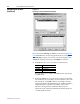
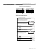
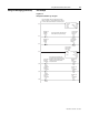
9. Type the number of bytes that are required for your I/O in the
Input Size and Output Size boxes.
Refer to Appendix B, pages B-23
to B-28 for all Bulletin 160
Assemblies.
In our example, we typed “4” in the Input Size and Output Size
boxes because we are using Output Assembly 21 and Input
Assembly 71.
10. Set the required rate for the data exchange selected in step 8.
(Click Help for more information.)
In our example using Polled data exchange, we selected “Every
Scan” for the Poll Rate.
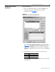
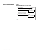
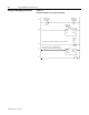
11. Click OK. If you changed any settings, a Scanner Applet asks if it
is OK to unmap the I/O. Click Yes to continue. The Edit I/O
Parameters dialog box closes and then the Scanner Module dialog
box (Figure 6.10
) reappears. You will map the I/O in the next
section in this chapter.
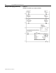
Mapping the Drive Data in the Scanner
Data from I/O messages must be mapped in the scanner. This
mapping determines where a ladder logic program can find data that
is passed over the network. You must map both the Input I/O and the
Output I/O.
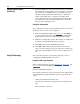
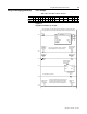
Mapping the Input I/O
1. In the Scanner Module dialog box, click the Input tab. (If
necessary, right-click the scanner in the configuration view
(Figure 6.9) to display this dialog box.)
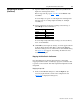
Data Exchange Rate to Set
Strobed N/A
Polled Poll Rate
Change of State Heartbeat Rate
Cyclic Send Rate