60-NX3 Chassis Mount (Series C) User Manual Supplement
Important User Information Solid-State equipment has operational characteristics differing from those of electromechanical equipment. “Safety Guidelines for the Application, Installation and Maintenance of Solid-State Controls” (Publication SGI-1.1) describes some important differences between solid-state equipment and hard-wired electromechanical devices.
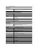
Contents Exceptions to Drive User Manual . . . . . . . . . . . . . . . . . . . . . . . . . . . . . . . . . . . . . . . . 1 Specifications . . . . . . . . . . . . . . . . . . . . . . . . . . . . . . . . . . . . . . . . . . . . . . . . . . . . . . . 1 Drive Rating . . . . . . . . . . . . . . . . . . . . . . . . . . . . . . . . . . . . . . . . . . . . . . . . . 1 Input/Output Ratings . . . . . . . . . . . . . . . . . . . . . . . . . . . . . . . . . . . . . . . . . . 1 Environmental Specifications . . . . . . .
ii
160-NX3 Series C Drive These instructions are intended to be used as a supplement to the drive user manual. For information regarding drive programming and operation, refer to the 160 SSC™ Variable Speed Drive (Series C) User Manual, Publication 0160-5.17ML. Exceptions to Drive User Manual Important: Set P42 - [Motor Overload Current] to motor nameplate full load amps (FLA). Settings that are not within Min / Max levels will cause premature failure of the product.
2 160-NX3 Series C Drive Control Inputs Control Input Type For dry contact closure input - drive has an internal 12V power supply that provides 10mA (typical) current. Also accepts open collector/solid-state input with maximum leakage current of 50µA. Optional 24V DC interface allows use of 24V DC “sink logic” inputs.
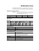
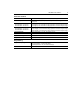
160-NX3 Series C Drive 3 Protective Features Overcurrent 200% hardware limit (16 amps), 300% instantaneous fault (24 amps) Excessive Temperature Embedded temperature sensor trips if heatsink temperature exceeds 95 degrees C (203 degrees F) Over Voltage Drive Rated Input = 200-240V AC Drive Rated Input = 380-460V AC DC Bus voltage is monitored for safe operation Overvoltage trip occurs at 400V DC bus voltage (equivalent to 290V AC incoming line voltage).
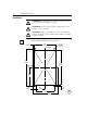
4 160-NX3 Series C Drive Installation ! ! ! ATTENTION: To guard against electrical shock, disconnect from power source before installing or servicing. ATTENTION: Do not touch drive surfaces. Temperatures are hot enough to cause severe burns. ATTENTION: After system installation, remove the debris label from the unit. Failure to remove this label may result in overheating or nuisance tripping. Cut-out and Mounting Detail For Customer Panel 1 8 (0.31) ∅ 5.5 (0.22) 6 Holes 114 (4.49) (Heatsink) 195 (7.
160-NX3 Series C Drive Item Qty. Description Required to Install A 8 3.2 mm (0.125 in.) Spacer 6 B 8 #10-32 Sealing Screw 6 2 3 A Top Torque to 1.35 N-m (12 lb-in) B #10-32 × .63 in Sealing Screw Customer Panel Max. 4.1 mm (0.16 in) Min. 1.5 mm (0.06 in) Outside Inside Heatsink Customer Panel Mounting holes intended to support weight of Allen-Bradley enclosed drives only. Gasket Spacer Thickness: 3.2 mm (0.
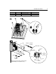
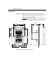
6 160-NX3 Series C Drive Dimensions Important: 130 (5.12) 114 (4.49) Bulletin 160 drives installed in user supplied enclosures are mounted to allow the heatsink to extend outside the enclosure. Use the information below in combination with the enclosure manufacturer’s guidelines for sizing. Clearances: There must be a minimum of 12.5 mm (0.5 in.) around all sides of the drive module, 100 mm (4 in.) on the top and bottom of the heatsink, and 50 mm (2 in.) on the sides of the heatsink. 92 ➊ (3.
Publication 0160-5.33 — February 2001 P/N 194406 (02) Copyright 2001 Rockwell International Corporation. All rights reserved. Printed in USA.