
Reference Manual User Manual

20 Rockwell Automation Publication 1606-RM001B-EN-P - August 2013
Bulletin 1606 Switched Mode Power Supplies
23.2 Back-feeding Loads
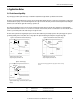
Loads such as decelerating motors and inductors can feed voltage back to the power supply. This feature is also called return voltage immunity or
resistance against Back- E.M.F. (E
lectro Magnetic Force).
This power supply is resistant and does not show malfunctioning when a load feeds back voltage to the power supply. It does not matter whether the
power supply is on or off.
The maximum allowed feed-back-voltage is 35V DC.
23.3 External Input Protection
The unit is tested and approved for branch circuits up to 30A (UL) and 32A (IEC). An external protection is only required if the supplying branch has an
ampacity greater than this. Check also local codes and local requirements. In some countries local regulations might apply.
If an external fuse is necessary or utilized, minimum requirements need to be considered to avoid nuisance tripping of the circuit breaker. A minimum
value of 10A B- or C-Characteristic breaker should be used.
23.4 Output Circuit Breakers
Standard miniature circuit breakers (MCB’s or UL 1077 circuit breakers) are commonly used for AC-supply systems and may also be used on 24V
branches.
MCB’s are designed to protect wires and circuits. If the ampere value and the characteristics of the MCB are adapted to the wire size that is used, the
wiring is considered as thermally safe regardless of whether the MCB opens or not.
To avoid voltage dips and under-voltage situations in adjacent 24V branches which are supplied by the same source, a fast (magnetic) tripping of the
MCB is desired. A quick shutdown within 10ms is necessary corresponding roughly to the ride-through time of PLC's. This requires power supplies with
high current reserves and large output capacitors. Furthermore, the impedance of the faulty branch must be sufficiently small in order for the current to
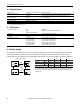
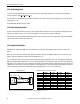
actually flow. The best current reserve in the power supply does not help if Ohm’s law does not permit current flow. The following table has typical test
results showing which B- and C-Characteristic MCBs magnetically trip depending on the wire cross section and wire length.
*) Don’t forget to consider twice the distance to the load (or cable length) when calculating the total wire length (+ and – wire).
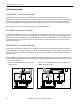
Fig.23-4 Test circuit
Maximal wire length
*)
for a fast (magnetic) tripping:
0.75mm² 1.0mm² 1.5mm² 2.5mm²
C-2A 29m 40m 56m 82m
C-3A 26m 35m 50m 77m
C-4A 21m 28m 36m 53m
C-6A 8m 10m 14m 25m
C-8A 4m 7m 11m 18m
C-10A 1m 2m 3m 6m
B-6A 17m 24m 35m 53m
B-10A 12m 16m 23m 32m
B-13A 9m 13m 20m 29m
B-16A 4m 7m 9m 17m
B-20A 1m 1m 2m 2m
MCB
Power Supply
AC
DC
+
-
+
-
Load
Wire lengt h
S1... Fault simulation switch
S1