
Reference Manual User Manual


24 Rockwell Automation Publication 1606-RM001B-EN-P - August 2013
Bulletin 1606 Switched Mode Power Supplies
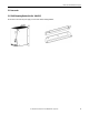
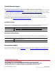
23.12 Mounting Orientations
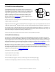
Mounting orientations other than all terminals on the bottom require a reduction in continuous output power or a limitation in the maximum allowed
ambient temperature. The amount of reduction influences the lifetime expectancy of the power supply. Therefore, two different derating curves for
continuous operation can be found below:
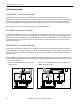
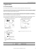
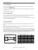
Curve A1Recommended output current.
Curve A2Max allowed output current (results in approximately half the lifetime expectancy of A1).
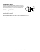
Enclosure:Rittal Typ IP66 Box PK 9522 100, plastic, 254x180x165mm
Load: 24V, 16A; (=80%) load is placed outside the box
Input:230Vac
Temperature inside enclosure: 53.5°C (in the middle of the right side of the power supply with a distance of 2cm)
Temperature outside enclosure: 25.3°C
Temperature rise:28.2K
Fig.23-5:
Mounting Orientation
A
(Standard
orientation)
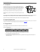
Fig.23-6:
Mounting Orientation
B
(Upside down)
Fig.23-7:
Mounting Orientation
C
(Table-top mounting)
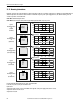
Fig.23-8:
Mounting Orientation
D
(Horizontal cw)
Fig.23-9:
Mounting Orientation
E
(Horizontal ccw)
Po w er
Supply
OUTPUTINPUT
Output Current
0
10 20 30 40
60°C
6
12
18
24A
50
A
1
Ambient Temperature
Po w e r
Supply
OUTPUTINPUT
Output Current
0
10 20 30 40
60°C
6
12
18
24A
50
Ambient Temperature
A
2
A
1
Output Current
0
10 20 30 40
60°C
6
12
18
24A
50
Ambient Temperature
A
1
A
2
Po w er
Supply
OUTPUTINPUT
Output Current
0
10 20 30 40
60°C
6
12
18
24A
50
Ambient Temperature
A
1
A
2
Po w er
Supply
OUTPUTINPUT
Output Current
0
10 20 30 40
60°C
6
12
18
24A
50
Ambient Temperature
A
1
A
2