
Reference Manual User Manual


6 Rockwell Automation Publication 1606-RM001B-EN-P - August 2013
Bulletin 1606 Switched Mode Power Supplies
6. Output
Output voltage nom. 24V
Adjustment range min. 24-28V guaranteed
max.
30V
****)
at clockwise end position of potentiometer
Factory settings typ. 24.1V ±0.2%, at full load, cold unit, in “single use” mode
typ. 24.1V ±0.2%, at full load, cold unit, in “parallel use” mode
typ. 25.1V at no load, cold unit, in “parallel use” mode
Line regulation max. 10mV 85-300Vac
Load regulation max. 100mV in “single use” mode: static value, 0A 20A;
see Figure 6-1
typ. 1000mV in “parallel use” mode: static value, 0A 20A,
see Figure 6-2
Ripple and noise voltage max. 50mVpp 20Hz to 20MHz, 50Ohm
Output current nom. 20A at 24V, ambient temperature <60°C, see Figure 6-1
nom.
24A
*)
at 24V, ambient temperature <45°C, seeFigure 6-1
nom. 17.1A at 28V, ambient temperature <60°C, see Figure 6-1
nom.
20.6A
*)
at 28V, ambient temperature <45°C, see Figure 6-1
typ. 80A up to 15ms, output voltage stays above 20V, see Figure 6-4, This peak current is
available once every five seconds. Refer to Peak Current Capability on page 19 for
more peak current measurements.
Output power nom. 480W continuously available
nom.
576W
*)
Power Boost
® *)
Overload behaviour cont. currentoutput voltage > 13Vdc, see Figure 6-1
Hiccup
PLUS
mode
**)
output voltage < 13Vdc, see Figure 6-1
Short-circuit current min.
35A
***)
load impedance <10mOhm, see Figure 6-3
max.
45A
***)
load impedance <10mOhm, see Figure 6-1
max.
15A
***)
average (R.M.S.) current, load impedance 50mOhm, see Figure 6-3
min. 70A up to 15ms, load impedance <10mOhm, see Figure 6-4
typ. 100A up to 15ms, load impedance <10mOhm, see Figure 6-4
Output capacitance typ. 7 000μF included inside the power supply
*) Power Boost This power/ current is continuously allowed up to an ambient temperature of 45°C. Above 45°C, do not use this power/ current longer than a duty cycle of 10% and/ or not longer than 1 minute every 10 minutes.
**) Hiccup
PLUS
Mode At heavy overloads (when output voltage falls below 13V), the power supply delivers continuous output current for 2s. After this, the output is switched off for approx. 18s before a new start attempt is automatically
performed. This cycle is repeated as long as the overload exists. If the overload has been cleared, the device will operate normally. See Figure 6-3
***) Discharge current of output capacitors is not included.
****) This is the maximum output voltage which can occur at the clockwise end position of the potentiometer due to tolerances. It is not guaranteed value which can be achieved. The typical value is about 28.5V (in “single use” mode).
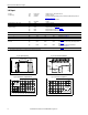
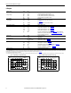
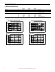
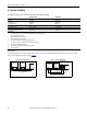
Fig. 6-1: Output voltage vs. output current, typ. Fig. 6-2: Output voltage in “parallel use” mode, typ.
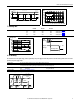
Fig. 6-3: Short-circuit on output, Hiccup
PLUS
mode, typ.
Fig. 6-4: Dynamic overcurrent capability, typ.
Output Voltage
(Single Use, typ.)
0
025
4
8
12
28V
16
20
24
40A155 10 20 30 35
Adjustment
Range
Output Current
Continuous
current
Fa c t or y
setting
Hi ccup
mode
Output Voltage
(Parallel Use, typ.)
22V
0816
23V
24V
25V
29V
26V
27V
28V
24A20124
Adjustment
Range
Fa c t or y
setting
Output Current